Chevrolet Equinox Service Manual: Intake Manifold Cleaning and Inspection Intake and Forced Induction Intake Manifold
Intake Manifold Cleaning ProcedureRemove any remaining gasket and/or gasket material from thefollowing:Throttle bodyIntake manifoldClean the following intake manifold areas in solvent.Intake manifold gasket sealing areasIntake manifold passagesBrake booster hose passageEvaporative emission (EVAP) solenoid passagePositive crankcase ventilation (PCV) vacuum hosepassages
Warning:Refer toSafety Glasses Warning.
Dry the intake manifold and throttle body with compressedair.Inspection Procedure
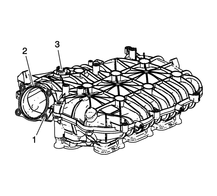
Inspect the intake manifold for the followingconditions:Damage to the throttle body bolt holes-(1)Damage, debris or restrictions to the PCV system hoseports-(3)Damage to the gasket sealing surface for the throttlebody-(2)

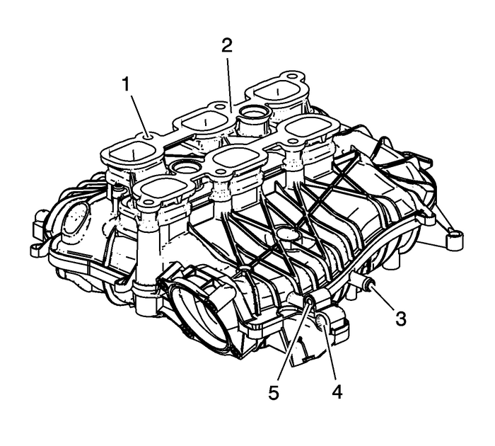
Inspect the intake manifold for the followingconditions:Damage, debris or restrictions to the brake vacuum boosterhose port-(3)Damage to the intake manifold boltbosses-(1)Damage to the EVAP purge solenoid mountingboss-(5)Damage, debris or restrictions to the EVAP purge solenoidport-(4)Gouges or damage to the intake manifold sealing surfaces(2)

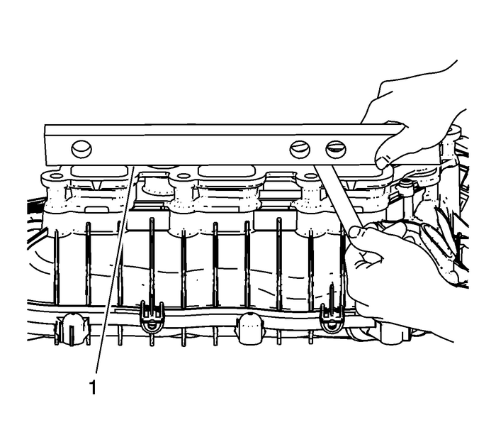
Inspect the intake manifold sealing surface-(1)for warpage.Locate a straight edge across the intake manifold sealingsurface.Insert a feeler gauge between the intake manifold and thestraight edge. An intake manifold with warpage in excess of0.50-mm (0.020-in) must be replaced.Repair or replace the intake manifold as necessary.
 Intake and Exhaust Camshaft, Bearing Cap, and Lash Adjuster Removal (LAF, LEA, or LUK) Valvetrain Valve Actuating Assembly Valve Tappets/Lifters
Intake Camshaft and Components RemovalRemove the intake camshaft position actuator solenoid valvebolt-(1) and valve-(2).Remove the rear cylinder head coverplate-(1).Remove the intake camshaft bearing ...
 Intake Manifold Cover Replacement Intake and Forced Induction Intake Manifold
Intake Manifold Cover ReplacementCalloutComponent Name1Intake Manifold Cover BoltCaution:Refer toFastener Caution.Tighten10-Y(89-lb-in)2Intake Manifold CoverProcedureRemove the oil cap before removing ...
Other materials:
Sunroof Drain Inspection and Cleaning Moonroof/Sunroof
Drain Hose RoutingNote:If the headliner is wet DO NOT remove any interior trim. Dothe Plugged Drain Hose test first.A drain trough encircles the sunroof window panel and wateris drained off by the drain hoses located at each corner of thehousing. A drain channel spans across the sunroof module at th ...
