Chevrolet Equinox Service Manual: Intake and Exhaust Camshaft, Bearing Cap, and Lash Adjuster Removal (LAF, LEA, or LUK) Valvetrain Valve Actuating Assembly Valve Tappets/Lifters
Intake Camshaft and Components Removal
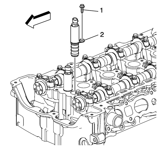
Remove the intake camshaft position actuator solenoid valvebolt-(1) and valve-(2).
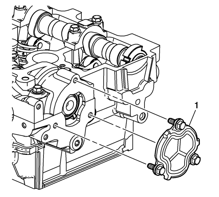
Remove the rear cylinder head coverplate-(1).
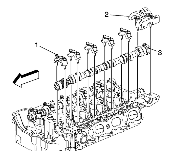
Remove the intake camshaft bearing rear cap bolts andcap-(2).
Note:Remove each bolt on each cap one turn at a time until thereis no spring tension pushing on the camshaft.
Mark camshaft caps to ensure they are installed in the sameposition.Remove the intake camshaft cap bolts.Remove the camshaft caps-(1).Remove the intake camshaft-(3).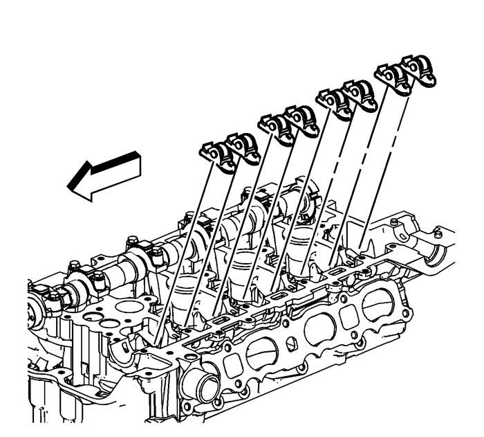
Note:Keep all of the roller finger followers and hydraulic lashadjusters in order so that they can be reinstalled in theirrespective locations.
Remove the intake camshaft roller finger followers.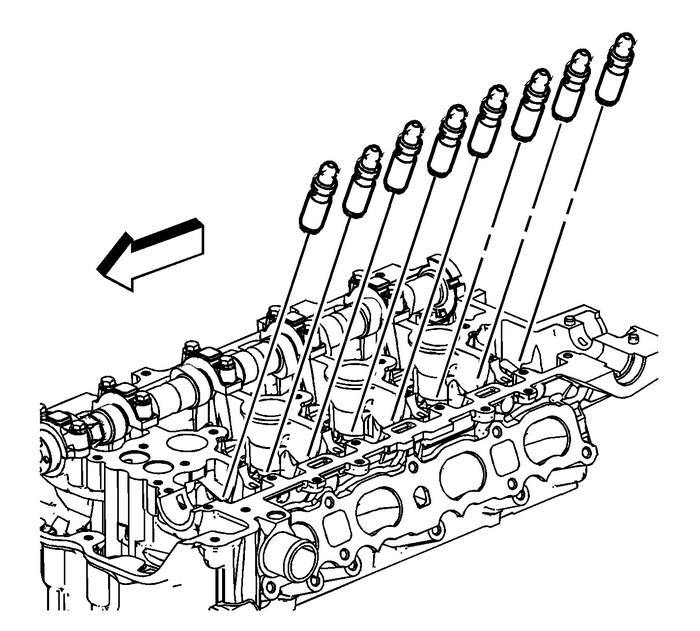
Remove the hydraulic lash adjusters.Exhaust Camshaft and Components Removal
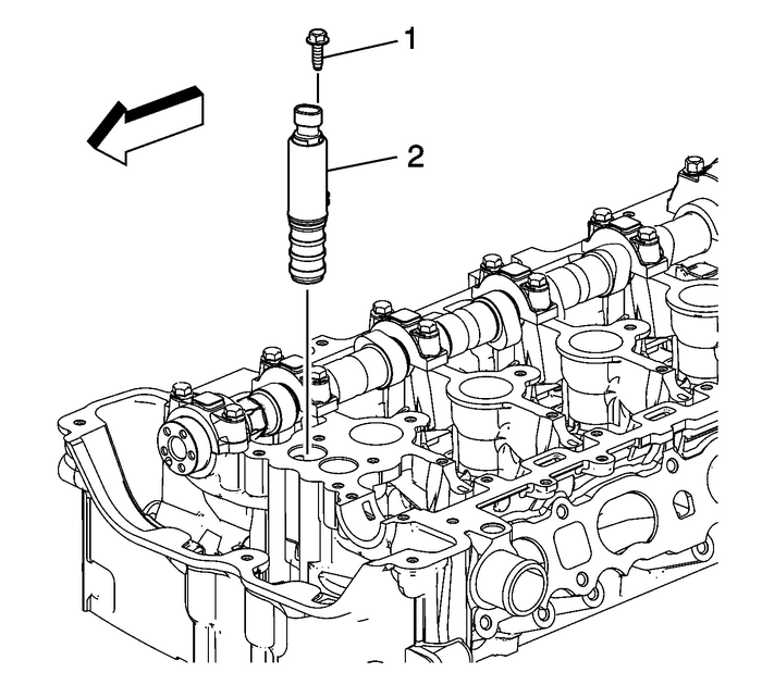
Remove the exhaust camshaft position actuator solenoid valvebolt-(1) and valve-(2).
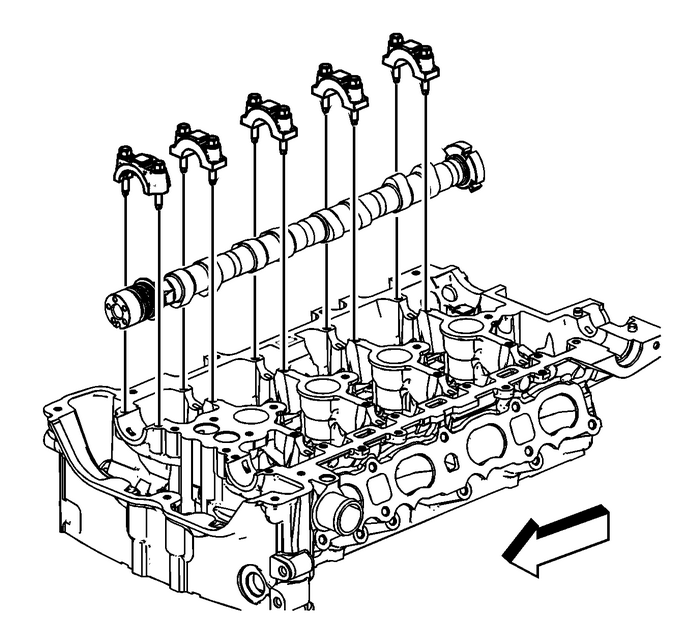
Note:Remove each bolt on each cap one turn at a time until thereis no spring tension pushing on the camshaft.
Mark camshaft caps to ensure they are installed in the sameposition.Remove the exhaust camshaft cap bolts.Remove the camshaft caps ensuring they are marked andrefitted in same position on assembly.Remove the exhaust camshaft.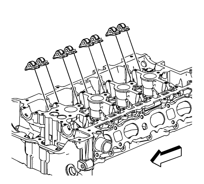
Note:Keep all of the roller finger followers and hydraulic lashadjusters in order so that they can be reinstalled in theirrespective locations.
Remove the exhaust camshaft roller finger followers.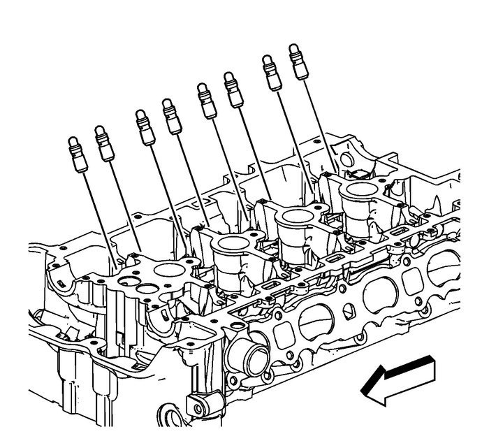
Remove the hydraulic lash adjusters.
 Water Outlet Installation Engine Cooling
Install the NEW water outlet seals-(3)and-(4).Install the water outlet-(2).Caution:Refer toFastener Caution.Install the water outlet bolts-(1) and tighten to10-Y(89-lb-in). ...
 Intake Manifold Cleaning and Inspection Intake and Forced Induction Intake Manifold
Intake Manifold Cleaning ProcedureRemove any remaining gasket and/or gasket material from thefollowing:Throttle bodyIntake manifoldClean the following intake manifold areas in solvent.Intake manifold ...
Other materials:
Front Wiper Blade Replacement
To replace the wiper blade:
Pull the wiper assembly away
from the windshield.
Lift up on the latch in the
middle of the wiper blade
where the wiper arm attaches.
With the latch open, pull the
wiper blade down toward the
windshield far enough to
release it from ...
