Chevrolet Equinox Service Manual: Control Valve Lower Body and Upper Body Replacement Automatic Transmission Unit
Removal ProcedureRemove the control valve body cover. Refer toControl Valve Body Cover Replacement.
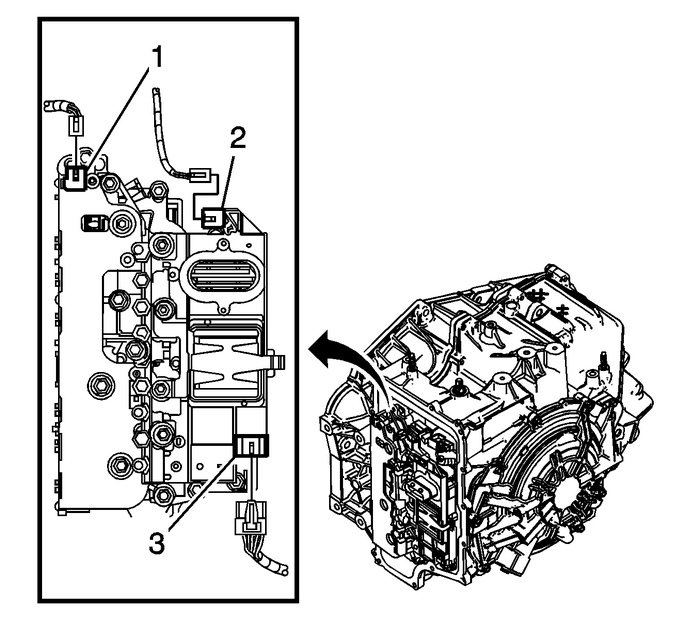
Disconnect the input speed sensor electricalconnector-(1).Disconnect the output speed sensor electricalconnector-(2).Disconnect the shift position switch electricalconnector-(3).
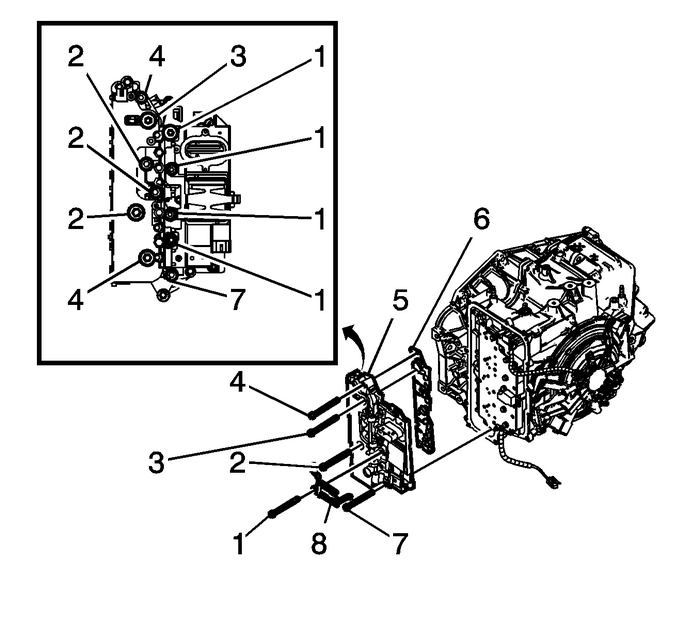
Remove the 4-control valve bodybolts-(1) M6-x-80.Position the control solenoid valve spring-(8) tothe side. Spring will be released with removal of lower controlvalve body.Remove the 2-control valve bodybolts-(4) M6-x-65.Remove the control valve body bolt-(3)M6-x-42.Remove the 3-control valve bodybolts-(2) M6-x-95.Remove the control valve body bolt-(7)M6-x-55.Remove the control solenoid valve body and transmissioncontrol module (TCM) assembly-(5).
Caution:Use care when removing or installing the filter plateassembly. A broken or missing retaining tab may not adequatelysecure the filter plate to the control solenoid valve assembly,resulting in possible damage or contamination.
Remove the control solenoid valve body assembly filterplate-(6).Discard the filler plate. It is not reusable.Inspect the pressure switch manifold seals for damage orcontamination. Replace the control solenoid valve assembly asnecessary.Inspect the upper channel plate bolt holes for damage,peening or burnelling. Any damage around the bolt holes near thePCS switch feed holes could cause leakage around the PCS switchseals. Replace the upper channel plate as necessary.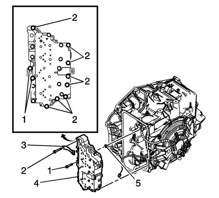
Remove the 8-control valve bodybolts-(2) M6-x-65.Remove the 2-control valve bodybolts-(1) M6-x-55.Remove the manual shaft detentassembly-(3).Remove the control valve body assembly-(4).The control solenoid valve spring can now be fully removedfrom the lower control valve body assembly.
Note:The clutch fluid passage seal is not reusable.
Remove the1–2–3–4-clutch fluidpassage seal-(5).Installation Procedure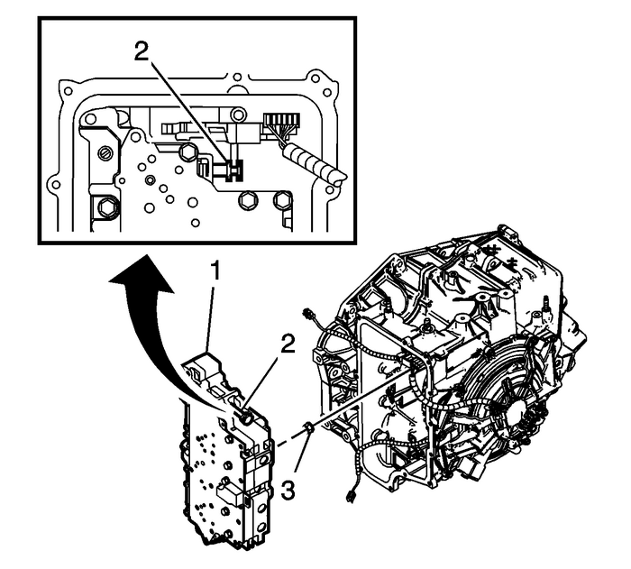
Note:The clutch fluid passage seal is not reusable.
Install a NEW1–2–3–4-clutch fluidpassage seal-(3).Note:
Ensure the control solenoid valve spring is attached to thelower control valve body assembly.Align the manual valve-(2) to the detent leverassembly while installing the lower control valve bodyassembly.Install the control valve bodyassembly-(1).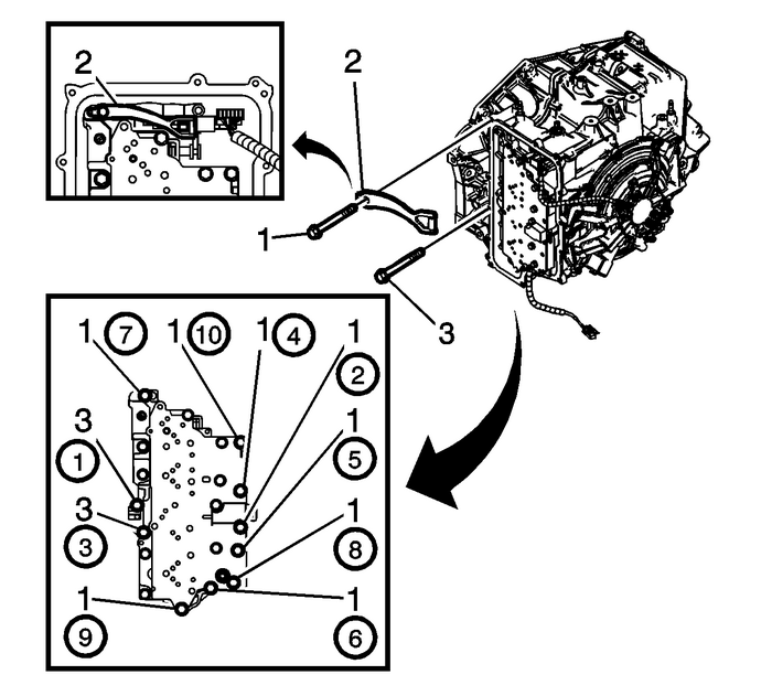
Note:Ensure proper alignment of the detent assembly to the detentlever assembly with position switch while tightening the bolt. Thedetent assembly can move and hit the valve body assembly that couldcause improper engagement with the detent lever assembly.
Install the manual shaft detentassembly-(2).Caution:Refer toFastener Caution.
Note:Install all bolts before tightening, then tighten inspecified sequence.
Install the 8-control valve bodybolts-(1) M6-x-65 and tighten to12-Y(106-lb-in).Install the 2-control valve bodybolts-(3) M6-x-55 and tighten to12-Y(106-lb-in).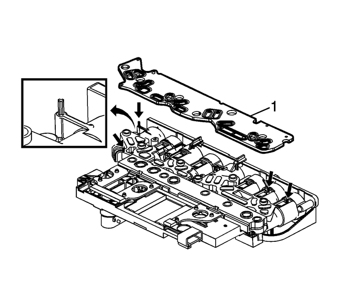
Caution:Use care when removing or installing the filter plateassembly. A broken or missing retaining tab may not adequatelysecure the filter plate to the control solenoid valve assembly,resulting in possible damage or contamination.
Install a NEW control solenoid valve assembly filterplate-(1).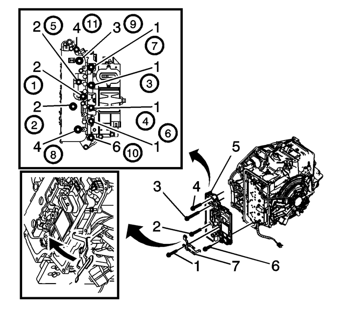
Install the control solenoid valve body and TCMassembly-(5).Rotate the control solenoid valve spring-(7) intoposition.
Note:Install all bolts before tightening, then tighten inspecified sequence.
Install the 4-control valve bodybolts-(1) M6-x-80.Install the control valve body bolt-(6)M6-x-55.Install the 3-control valve bodybolts-(2) M6-x-95.Install the control valve body bolt-(3)M6-x-42.Install the 2-control valve bodybolts-(4) M6-x-65 and tighten to12-Y(106-lb-in).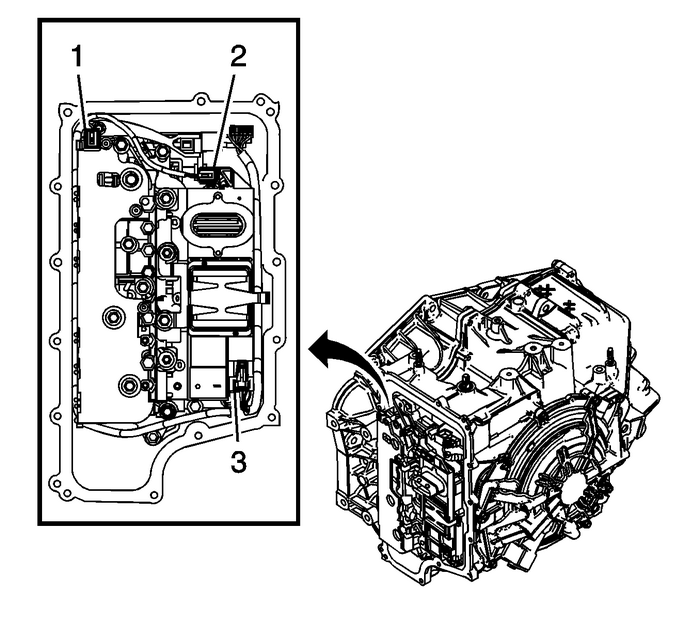
Connect the input speed sensor electricalconnector-(1).Connect the output speed sensor electricalconnector-(2).Connect the shift position switch electricalconnector-(3).Install the control valve body cover. Refer toControl Valve Body Cover Replacement.For transmission control module programming and setup. RefertoControl Module References.
Note:After an internal transmission repair or internal partreplacement the Reset Transmission Adapts procedure should beperformed.
Perform the Reset Transmission Adapts. Refer toReset Transmission Adapts. Input Speed Sensor Replacement Automatic Transmission Unit
Removal ProcedureRemove the control solenoid valve and transmission control module assembly. RefertoControl Solenoid Valve and Transmission Control Module Assembly Replacement.Disconnect the input spe ...
 Control Solenoid Valve and Transmission Control Module Assembly Replacement Automatic Transmission Unit
Removal ProcedureRemove the transmission control valve body cover. Refer toControl Valve Body Cover Replacement.Disconnect the input speed sensor electrical connector-(1).Disconnect the output speed s ...
Other materials:
Power Windows Description and Operation Side Windows
Power Windows System ComponentsThe power window system consists of the following components:Driver window switchPassenger window switchLeft rear window switchRight rear window switchWindow motors in each of the doors30A FuseBody control module (BCM)K9Body Control ModuleS79RRWindow Switch - Right Rea ...
