Chevrolet Equinox Service Manual: Torque Converter and Differential Housing Assembly Assemble Automatic Transmission Unit
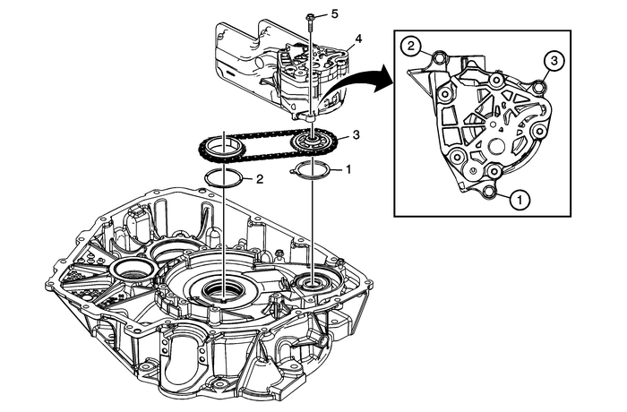
| Table 1: | Pump Assembly Installation |
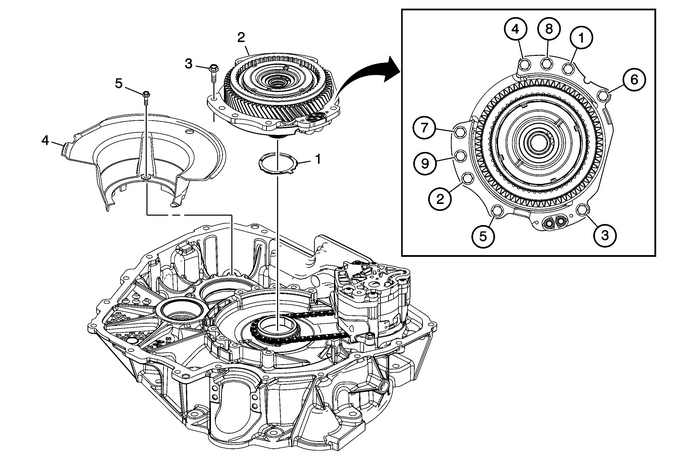
| Table 2: | Transfer Drive Gear Assembly Installation |

1 | Driven Sprocket Thrust Washer |
2 | Drive Sprocket Thrust Washer |
3 | Install Drive Link Assembly Note:Install as an assembly. |
4 | A/Trans Fluid Pump Assembly Note:Rotating the drive sprocket and link assembly while installing the oil pump will aidin aligning the driven sprocket and oil pump drive shaft splines. |
5 | A/Trans Fluid Pump Bolt-M6-x-25-(Qty: 3) Caution:Refer toFastener Caution. Procedure: Tighten in sequence shown. Tighten12-Y (106-lb-in). |

1 | Drive Sprocket Thrust Washer |
2 | Front Differential Transfer Drive Gear Support Assembly |
3 | Front Differential Transfer Drive Gear Support Bolt-M8-x-25 (Qty: 9) Caution:Refer toFastener Caution. Procedure Tighten in sequence shown. Tighten10-Y (89-lb-in) plus 50-degrees-±-4-degrees. Special Tools: EN 45059 Angle Meter For equivalent regional tools, refer toSpecial Tools. |
4 | Front Differential Carrier Baffle |
5 | Front Differential Carrier Baffle Bolt-M6-x-25 Tighten12-Y (106-lb-in). |
 1-2-3-4 Clutch Plate and Low and Reverse Clutch Installation Automatic Transmission Unit Automatic Clutches
Table 1: Piston and Spring InstallationTable 2: 1-2-3-4 Clutch Plates and Low Reverse Clutch InstallationTable 3: Low and Reverse Clutch Plate InstallationPiston and Spring InstallationPiston and Spri ...
 3-5-Reverse and 4-5-6 Clutch Housing Disassemble Automatic Transmission Unit
Table 1: Reluctor Wheel and Piston RemovalTable 2: Clutch Plate RemovalTable 3: 4–5–6 Clutch Hub RemovalTable 4: 4–5–6 Clutch Piston RemovalReluctor Wheel and Piston RemovalReluctor Wheel and ...
Other materials:
Fastener Tightening Specifications - Propeller Shaft Assembly Driveshafts Propeller Shaft Assembly
Fastener Tightening SpecificationsApplicationSpecificationMetricEnglishCenter Bearing-to-Vehicle Underbody Bolts25-Y19-lb-ftPropeller Shaft-to-Rear Differential Flange Bolts50-Y37-lb-ftPropeller Shaft-to-Transfer Case Flange Bolts35-Y25-lb-ft ...
