Chevrolet Equinox Service Manual: Piston and Connecting Rod Assemble Engine Block Cylinder Block Piston Assembly
Special ToolsEN-46121 Connecting Rod Guide Pin SetEN-46745 Piston Pin Clip Remover/Installer
For equivalent regional tools, refer toSpecial Tools
Piston and Piston Pin Installation Procedure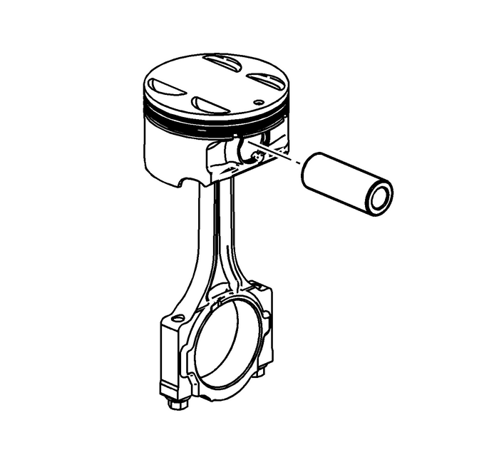
Note:
The piston is directional and must be installed in the engine block in the properdirection. The dot on the top of the piston must face the front of the engine.The piston is model dependent and may not appear exactly as shown.Lubricate the piston pin bores in the piston and the connecting rod with GM prelubelubricant. Refer toAdhesives, Fluids, Lubricants, and Sealersfor recommended lubricant.Assemble the piston and piston pin to the connecting rod. Properly orient the pistonwhen reusing a marked connecting rod.Align the piston pin bore with the connecting rod pin bore.Slide the piston pin into the piston and the connecting rod.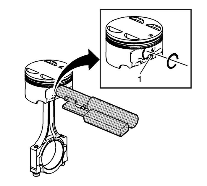
Note:New piston pin retainers must be used. Never reuse the piston pin retainers.
Install NEW piston pin retainers using the EN-46745 remover/installer. Align the EN-46745 remover/installer to the notch-(1) in the piston.Ensure that the piston pin retainers are fully seated in their grooves.Repeat these procedures for the remaining pistons.Piston Ring Installation Procedure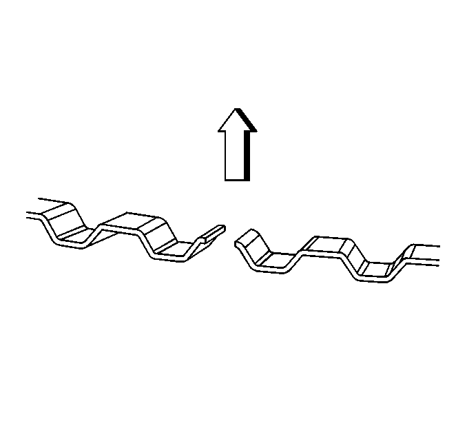
Properly orient the oil control ring expander as shown before installation. The endsof the expander must be facing toward the top of the piston.
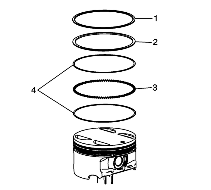
Using a piston ring expander, install the oil control ring assembly using the followingprocedure:Install the expander ring-(3).Install the 2-oil scraper rings-(4). Expand the rings only enough to clear the pistondiameter. Overexpanding the piston rings will distort or crack the rings.
Note:The lower compression piston ring-(2) is thicker and will not fit in the upper compressionrings-(1) position.
Install the lower compression piston ring -(2) onto the piston with the mark facingthe top of the piston.Note:For the LY7, the upper compression ring is symmetrical and may be installed eitherside up. For all other RPO’s, the mark on the piston ring should face the top of thepiston.
Install the upper compression piston ring -(1) onto the piston with the mark facingthe top of the piston, if required.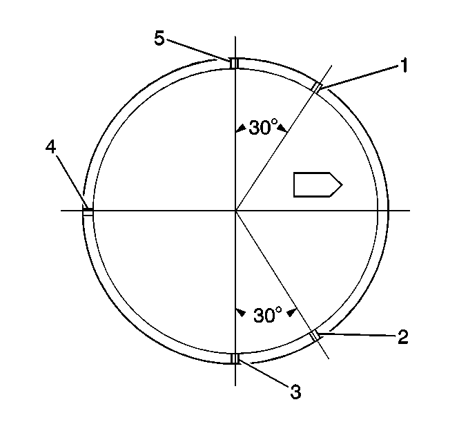
Once the rings are installed, set the ring gaps for the oil control, second and topring as follows. Use the piston location arrow for reference.Lower oil control ring – position-1Upper oil control ring – position-2Top Ring – position-3Oil control ring expander – position-4Second ring – position-5Connecting Rod Bearing Installation Procedure
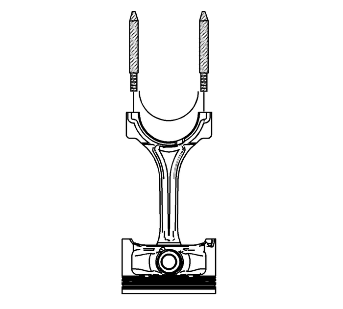
Note:If the connecting rod bearings have been used in a running engine, you must replacethem with NEW connecting rod bearings for reassembly.
Clean the connecting rod and the connecting rod cap bearing bore with a lint-freecloth.Clean all the oil from behind the connecting rod bearing halves.Install NEW upper connecting rod bearings into position. Roll the bearing into positionso that the lock tang engages the alignment slot. The bearing must fit flush in theconnecting rod.Install the EN-46121 set into the connecting rod bolt holes.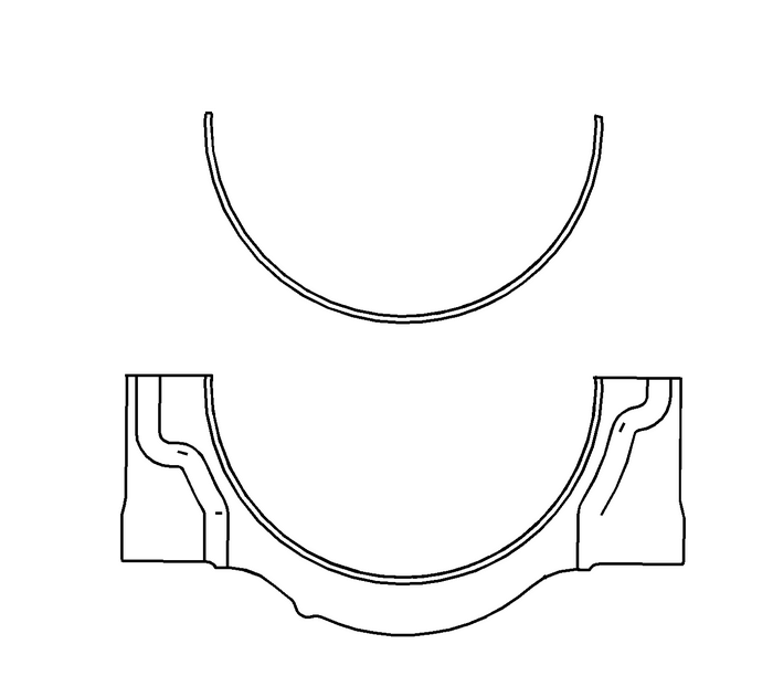
Install NEW lower connecting rod bearings into position in the connecting rod cap.Roll the bearing into position so that the lock tang engages the alignment slot. Thebearings must fit flush with the connecting rod cap.
 Engine Front Cover Installation Engine Block Cylinder Block Cyl Block Front Cover
Special Tools EN–46109 Guide PinsFor equivalent regional tools, refer toSpecial Tools.Install the 8-mm (0.315-in) guide from the EN–46109 pins into the cylinder block positions as shown.Install th ...
 Piston, Connecting Rod, and Bearing Removal Engine Block Cylinder Block Piston Assembly
Special ToolsEN 46121Connecting Rod Guide Pin SetFor equivalent regional tools, refer toSpecial Tools.Note:An arrow/dot showing proper piston orientation is located onthe top of the piston.If the conn ...
Other materials:
Rear Side Door Lower Molding Replacement Doors
Rear Side Door Lower Molding ReplacementCalloutComponent NamePreliminary ProceduresOpen the rear door in order to access the lower moldingretainers first.Using a trim-type tool, release the lower retainers followedby the upper retainers.1Rear Side Door Lower Molding Retainer(Qty:-10)2Rear Side Door ...
