Chevrolet Equinox Service Manual: Mode Valve Actuator Replacement
Chevrolet Equinox Service Manual / HVAC / Mode Valve Actuator Replacement

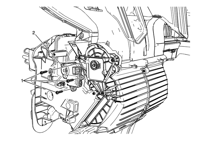
| Preliminary ProceduresRemove instrument panel insulator panel – leftside. Refer toInstrument Panel Insulator Panel Replacement - Left Side.Remove the communication interface module. Refer toCommunication Interface Module Replacement.Reposition any wiring or hoses to gain access to mode controlcam actuator. | |
1 | Mode Control Cam Actuator Screw (Qty:-3) Caution:Refer toFastener Caution. Tighten2.0-Y(18-lb-in) |
2 | Mode Control Cam Actuator ProcedureDisconnect wiring connector at actuator.Calibrate the mode control cam actuator. Refer toActuator Recalibration. |
 Mode Control Cam Replacement
Mode Control Cam ReplacementCalloutComponent NamePreliminary ProceduresDisconnect the negative battery cable. Refer toBattery Negative Cable Disconnection and Connection.Remove instrument Panel – le ...
 Mode Valve Actuator Replacement
Mode Valve Actuator ReplacementCalloutComponent NamePreliminary ProceduresRemove instrument panel insulator panel – leftside. Refer toInstrument Panel Insulator Panel Replacement - Left Side.Reposit ...
Other materials:
Oil Level Indicator and Tube Installation Engine Lubrication Oil Level Indicator Tube
Install a NEW O-ring on the oil level indicatortube.Install the oil level indicator and tube-(2) bysliding the tube down through the lower crankcase hole.Caution:Refer toFastener Caution.Install the oil level indicator tube bracketbolt-(1) and tighten to10-Y(89-lb-in). ...
© 2017-2026 Copyright www.cequinox.com

