Chevrolet Equinox Service Manual: Front Side Door Lock Cylinder Coding Locks Mechanical Locks

The door lock cylinder uses 6 of the 8-cutpositions, 3 through 8. The tumbler positions are staggered fromside to side, 3 on one side and 3 on the other, are notself-retaining, and are not snap in.
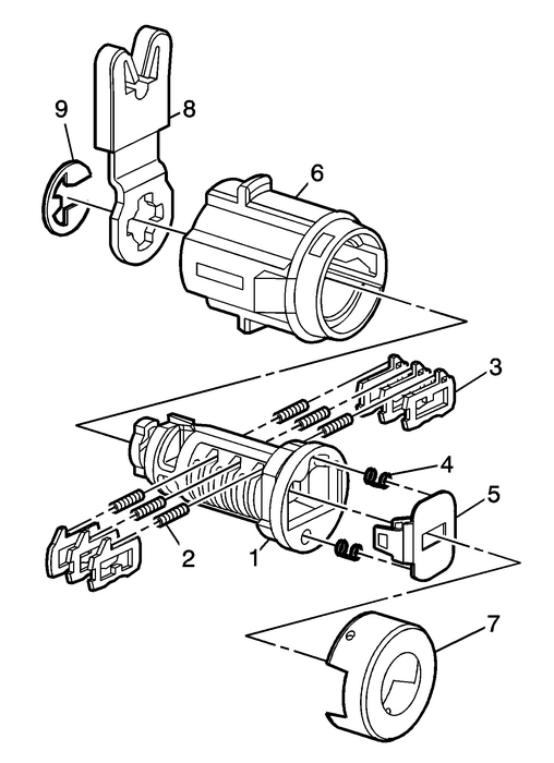
Note:All lock cylinders for side milled keys have right and lefttumblers. The location of the tooth of the tumbler determineswhether it is right of left. Illustrations in this procedure showthe right tumblers on the top and the left tumblers on the bottom.All tumblers are marked 1R, 1L, 2R, or 2L. The number being cutdepth and the letter meaning right or left.
Insert two springs-(4) into the two spring wellsin the head of the lock cylinder.Snap the shutter assembly-(5) onto the cylinder asis shown in the illustration.Hold the cylinder-(1) so the spring pockets facesup (spring pocket nearest to the back of the key head).Insert the tumbler springs-(2) into the3-spring pockets.Install the tumbler-(3) for key cut position threein the slot nearest to the back of the key head in the lockcylinder. Install the remaining tumblers, key cut positions 5 and7, following the key code and same process, use tumblers identifiedas 11 to 14. Tumbler 11 to used when key code cut is #1, 12 is #2,13 is #3 and 14 is #4.Check the correct loading of the tumblers by inserting thekey into the cylinder. All tumblers should be flush with the lockcylinder body.Turn the cylinder so the side spring wells faces up. Removethe key and hold the tumblers.Insert the tumbler springs into the 3-springpockets.The first tumbler closest to the front of the lock cylinderto be loaded will be the fourth key cut position, the fourth numberin the key code. Install the remaining tumblers for the key cutpositions 6 and 8, use tumblers identified as 1 to 4.Check the correct loading of the tumblers by inserting thekey into the cylinder. All of the tumblers should be flush with thelock cylinder body. Remove the key and hold the tumblers inplace.Insert key and lightly lubricate the cylinder body diameterand tumbler surfaces and a small amount in the head of the cylinderusing the supplied grease.Insert the lock cylinder-(1) onto thecase-(6). Remove the key.Align the lock cylinder cap-(7) and secure bypressing the cap into place with light hand pressure.Assemble the lever-(8) and thee-clip-(9) to retain the lever assembly as shown in theillustration.Insert the key and rotate the lock to check for properassembly and smooth operation. #09-00-89-029K: Key Cutting Procedure for Obtaining Replacement Key - (Jun 27, 2013) Keys and Keyless Entry
Subject:Key Cutting Procedure for Obtaining Replacement KeyModels: 2010-2014 Buick LaCrosse2011-2014 Buick Regal2012-2014 Buick Verano2010-2014 Cadillac SRX2013-2014 Cadillac ATS, XTS2010-2014 Chevro ...
 Theft Deterrent Module Replacement Immobilizer
Theft Deterrent Module ReplacementCalloutComponent NamePreliminary ProcedureRemove the steering column shrouds. Refer toSteering Column Shroud Replacement.1Theft Deterrent Module Bolt/Screw (Qty:-2)Ca ...
Other materials:
Inside Rearview Mirror Replacement Rearview
Inside Rearview Mirror ReplacementCalloutComponent Name1Inside Rearview Mirror ScrewCaution:Refer toFastener Caution.ProcedureRemove the inside rearview mirror cover, if equipped.Tighten2-Y (18-lb-in)2Inside Rearview MirrorProcedureDisconnect the electrical connector, if equipped.Adjust the mirror t ...
