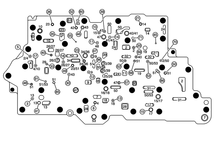
Chevrolet Equinox Service Manual: Control Valve Upper Body Spacer Plate Assembly Automatic Transmission Unit
Chevrolet Equinox Service Manual / Powertrain / Transmission/Transaxle / Control Valve Upper Body Spacer Plate Assembly Automatic Transmission Unit
Control Valve Upper Body Spacer Plate Assembly

| (2) | Line |
| (3) | Decrease |
| (4) | Converter Feed |
| (5) | TCC Release |
| (7) | Cooler Feed |
| (8) | Lube |
| (9) | Regulated Apply |
| (10) | Compensator Feed |
| (11) | Actuator Feed Limit |
| (13) | PCS Line |
| (14) | PCS R1/456 Clutch |
| (15) | Solenoid 1 |
| (16) | Solenoid 2 |
| (17) | CSV2 Enable |
| (18) | CSV3 Enable |
| (19) | R1/456 Clutch Feed |
| (20) | R1 Feedback |
| (21) | R1 Supply |
| (23) | PCS 35 Reverse Clutch |
| (24) | Reverse |
| (25) | 35 Reverse Clutch Feed |
| (26) | 35 Reverse Supply |
| (27) | 35 Reverse Feed |
| (28) | 35 Reverse Clutch |
| (29) | C35 Reverse Feedback |
| (30) | PCS 1234 Clutch |
| (31) | Drive |
| (32) | Drive Brake |
| (33) | Drive B |
| (34) | 26 Clutch/1234 Clutch Feed |
| (36) | 1234 Clutch Feed |
| (39) | Drive 1–6 |
| (40) | Latch Feed |
| (41) | CSV2 Latch |
| (42) | PCS 26 Clutch |
| (43) | 26 Clutch Feedback |
| (45) | 1234 Clutch Default |
| (46) | 456 Clutch Feed |
| (47) | 456 Clutch |
| (48) | PCS TCC |
| (50) | Exhaust Backfill |
| (51) | Exhaust |
| (53) | Void |
 Control Valve Upper Body Assembly - Upper Body Spacer Plate Side Automatic Transmission Unit
Control Valve Upper Body Assembly– Upper Body Spacer Plate Side(2)Line(3)Decrease(4)Converter Feed(5)TCC Release(6)TCC Apply(7)Cooler Feed(9)Regulated Apply(10)Compensator Feed(11)Actuator Feed Limi ...
 Differential Carrier Removal (6T40/45/50) Automatic Transmission Unit
Differential Carrier RemovalCalloutComponent Name1Front Differential Carrier Bearing Assembly2Differential Carrier Assembly3Final Drive Sun Gear ...
Other materials:
Brake Pedal Position Sensor Replacement Hydraulic Brakes Brake Pedal Assembly
Brake Pedal Position Sensor ReplacementCalloutComponent NamePreliminary ProcedureRemove the instrument panel insulator panel left side. RefertoInstrument Panel Insulator Panel Replacement - Left Side.Remove the communication interface module. Refer toCommunication Interface Module Replacement1Brake ...
© 2017-2026 Copyright www.cequinox.com

