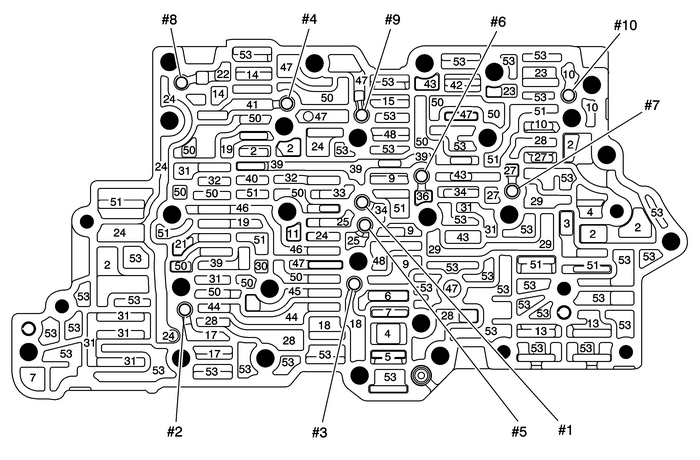
Chevrolet Equinox Service Manual: Control Valve Upper Body Assembly - Upper Body Spacer Plate Side Automatic Transmission Unit
Chevrolet Equinox Service Manual / Powertrain / Transmission/Transaxle / Control Valve Upper Body Assembly - Upper Body Spacer Plate Side Automatic Transmission Unit
Control Valve Upper Body Assembly– Upper Body Spacer Plate Side

| (2) | Line |
| (3) | Decrease |
| (4) | Converter Feed |
| (5) | TCC Release |
| (6) | TCC Apply |
| (7) | Cooler Feed |
| (9) | Regulated Apply |
| (10) | Compensator Feed |
| (11) | Actuator Feed Limit |
| (13) | PCS Line |
| (14) | PCS R1/456 Clutch |
| (15) | Solenoid 1 |
| (17) | CSV2 Enable |
| (18) | CSV3 Enable |
| (19) | R1/456 Clutch Feed |
| (21) | R1 Supply |
| (22) | R1 |
| (23) | PCS 35 Reverse Clutch |
| (24) | Reverse |
| (25) | 35 Reverse Clutch Feed |
| (27) | 35 Reverse Feed |
| (28) | 35 Reverse Clutch |
| (29) | 35 Reverse Clutch Feedback |
| (30) | PCS 1234 Clutch |
| (31) | Drive |
| (32) | Drive Brake |
| (33) | Drive B |
| (34) | 26 Clutch/1234 Clutch Feed |
| (36) | 1234 Clutch Feed |
| (39) | Drive 1–6 |
| (40) | Latch Feed |
| (41) | CSV2 Latch |
| (42) | PCS 26 Clutch |
| (43) | 26 Clutch |
| (44) | 1234 Clutch Default Feed |
| (45) | 1234 Clutch Default |
| (46) | 456 Clutch Feed |
| (47) | 456 Clutch |
| (48) | PCS TCC |
| (50) | Exhaust Backfill |
| (51) | Exhaust |
| (53) | Void |
 Control Valve Upper Body Assembly - Lower Body Spacer Plate Side Automatic Transmission Unit
Control Valve Upper Body Assembly– Lower Body Spacer Plate Side(2)Line(3)Decrease(5)TCC Release(6)TCC Apply(7)Cooler Feed(10)Compensator Feed(11)Actuator Feed Limit(14)PCS R1/456 Clutch(19)R1/456 Cl ...
 Control Valve Upper Body Spacer Plate Assembly Automatic Transmission Unit
Control Valve Upper Body Spacer Plate Assembly(2)Line(3)Decrease(4)Converter Feed(5)TCC Release(7)Cooler Feed(8)Lube(9)Regulated Apply(10)Compensator Feed(11)Actuator Feed Limit(13)PCS Line(14)PCS R1/ ...
Other materials:
Rear Toe Adjustment Wheels
Loosen the suspension adjustment link-to-frame fastenerenough to allow for movement.Note:If experiencing problems in adjusting the rear toe, replacethe existing nut with the service cam nut to eliminate theadjustment problem.Rotate the suspension adjustment nut in the directionnecessary to correct t ...
© 2017-2026 Copyright www.cequinox.com

