Chevrolet Equinox Service Manual: Strut Assembly Removal and Installation Strut Assembly
Removal Procedure

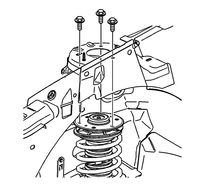
Remove the 3-upper strut mount bolts.Raise and support the vehicle. Refer toLifting and Jacking the Vehicle.Remove the wheel and tire assembly. Refer toTire and Wheel Removal and Installation.

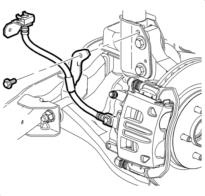
Remove the brake hose bracket bolt from the strut assembly.

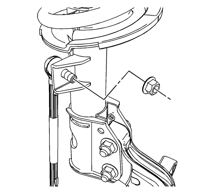
Remove the stabilizer link nut and separate the link from the strut assembly.

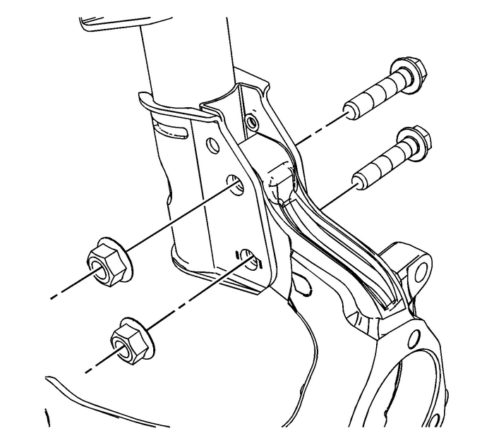
Remove the lower strut bolts and nuts.Remove the strut assembly from the vehicle.Installation Procedure

Position the strut assembly to the vehicle.
Caution:Refer toFastener Caution.
Install the 3-upper strut mount bolts and tighten to 25-Y (18-lb-ft).
Install the lower strut bolts and nuts and tighten to 185-Y (136-lb-ft).

Note:Inspect the stabilizer link seals for damage prior to installation. Replace as required.
Note:Do not allow the stabilizer link ball stud to rotate while installing the link nut.
Position the stabilizer link to the strut and install the nut and tighten the nutto 85-Y (63-lb-ft).
Position the brake hose bracket to the strut assembly and install the bolt and tightento 15-Y (11-lb-ft).Install the wheel and tire. Refer toTire and Wheel Removal and Installation.Lower the vehicle.Perform a wheel alignment. Refer toWheel Alignment Measurement.
 Trailing Arm Replacement Control Arms
Removal ProcedureRaise and support the vehicle. Refer toLifting and Jacking the Vehicle.Remove the tire and wheel. Refer toTire and Wheel Removal and Installation.Remove the park brake cable bolt from ...
 Lower Control Arm Ball Joint Replacement Suspension Ball Joints
Removal ProcedureRemove the lower control arm. Refer toLower Control Arm Replacement.Place the lower control arm in a vise or suitable holding device.Remove the ball joint rivets using the following p ...
Other materials:
#01-06-01-011H: Information on Engine Oil Consumption Guidelines - (Oct 29, 2013) Engine Lubrication
Subject:Information on Engine Oil Consumption GuidelinesModels: 2014 and Prior GM Cars and Gasoline-Powered Light Duty Trucks Under 8500-LB GVW This bulletin has been revised to add the 2013-2014 model years. Please discard CorporateBulletin Number 01-06-01-011G.All engines require oil to lubri ...
