Chevrolet Equinox Service Manual: Remote Control Door Lock, Theft Deterrent, and Remote Start Transmitter Package Installation
| Table 1: | Kit Contents |
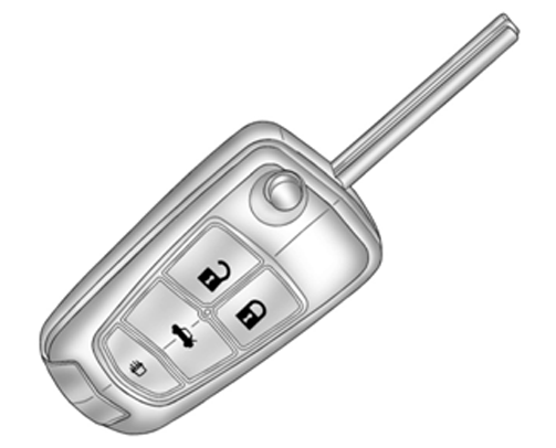
| Table 2: | Replacement Key Description |
20981984
1 | Hood Latch P/N 20941413 (MY10-11 Kit P/N 20981996) |
1 | Hood Latch P/N 22787039 (MY12 Kit P/N 22924978) |
1 | Hood Latch P/N 22909711 (MY13 Kit P/N 22957875) |
1 | Hood Latch P/N 23120089 (MY14 Kit P/N varies with TB4/TB5/X88/Z88 combinations) |
2 | Flipkey Transmitters with Uncoded Blade (NEW for kits ordered during MY14 and beyond,key P/N varies with TB4/TB5/X88/Z88) |
1 | Hood Switch Wiring Harness |
1 | Installation Instructions |
Important:The remote control transmitter and key shank can now be service separately using aspecial tool. Review procedure for details.
Note:Make sure to verify the current part numbers with the GM Service Parts Catalog.
Key Cutting Procedure for Obtaining Replacement KeyNote:Before installation of the remote start kit, the dealer must order the remote startkey (for keyless kits only).
13504199 | Uncoded | BTV & TB5 | 13504259 |
13500221 | Coded | BTV & TB5 | 13501514 |
20873620 | Uncoded | BTV & TB4 | 20873622 |
20835404 | Coded | BTV & TB4 | 20835400 |
BTV-Remote Engine Start TB4-Lift Gate TB5-Power Lift Gate | |||
Note:Make sure to verify the current part numbers with the GM Service Parts Catalog.
Note:This key cutting, key obtaining replacement applies to the United States and Canadaonly. Export dealers are to contact their local Technical Assistance Center (TAC)for further information.
Due to the uniqueness of the ignition/door lock key, special equipment is requiredto cut a key.
If you do not have the required equipment, you may order a cut/coded key through GMSPO.
To obtain replacement keys the following procedure is suggested:
Obtain the vehicle key code.U.S. Dealers: Access the “Key Code Look Up” application through GM GlobalConnect under the PartsWorkbench.
Canadian Dealers: Access the “KeyCode Look-Up” feature within the OEConnection D2DLink application.
Submit a part order through the GMSPO Parts System for a key blank. Be sure to includethe key code in the “note” field of the order.Do not order an uncoded key as you will receive a blank key that will require codingon the special equipment listed below.Important:The order will be shipped the same day if received by 12:00 p.m. (noon) EST, or within24 hours, Monday through Friday via FedEx (Canadian dealers will be charged for freightfor overnight (CSO3) orders).
Important:The remote control transmitter and the key shank can now be serviced using BO-51098Flip Key Blade Fixture.
Tip:The new key and transmitter will need to be programmed to the vehicle. Refer to programmingprocedure at the end of these instructions for details.

Parts Information (For Keyless Kits Only)
For part numbers and usage, refer to Key in Major Group 2, 2.187 in Part Group Index,of the appropriate parts catalog.
Important:As an alternate to Step 2, the following equipment can be purchased through 1-800-GM-TOOLSor by visiting www.GMDEsolutions.com (U.S.) or www.des-canada.ca (Canada).
General Motors highly recommends the use of the following key machines. General Motorshas identified superior equipment through testing and evaluation. General Motors believesthese sources and their equipment to be reliable. There may be additional manufacturersof such equipment. General Motors does not endorse, indicate any preference for orassume any responsibility for the equipment from these firms or for any such itemswhich maybe available for other sources.
Equipment InformationComputerized Duplicating and Code Cutting | Used to produce a key from a key code or duplicate | Barnes distribution BD Laser Code Cut & Duplicator GMDE Part # 425-9200000 |
Computerized Duplicating and Code Cutting | Used to produce a key from a key code or duplicate | Kaba Ilco Tricode HS Code Cut & Duplicator GMDE Part # 74-TRI-Code HS |
Machine Duplication | Used to produce a duplicate key from an existing key | Kaba Ilco Matrix S Duplicator GMDE Part # 74-Matrix S |
Updating the Transmitter to a Coded Key using BO-51098 Flip Key Blade Fixture
Note:Updating the transmitter to a coded key applies to the United States and Canada only.
Export dealers are to contact their local Technical Assistance Center (TAC) for further information.Due to the uniqueness of the ignition/door lock key, special equipment is requiredto cut a key.For equipment details, refer to Service Bulletiin #09-00-89-029J: Key Cutting Procedure for Obtaining ReplacementKey.If you do not have the required equipment, use Flip Key Blade Fixture Tool BO-51098to swap coded key from OE Transmitter and install on Accessory Transmitter. RefertoDoor Lock and Ignition Lock Folding Key Blade Removal and Installation.Tip:The new key and transmitter will need to be programmed to the vehicle. Refer to ProgrammingVehicle at the end of these instructions for details.
Special ToolsScan Tool with capability of communicating on GMLANService Programming System (SPS – TIS2WEB or equivalent)J-46079 Tire Pressure Monitor Diagnostic ToolBO-51098 Flip Key Blade FixtureProcedureNote:When calling the TCSC, you must use the Authorization Code from the kit.
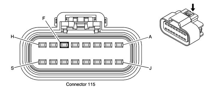
Remove hood latch and install new latch. Refer toHood Primary and Secondary Latch Replacement.Connect the hood switch wiring harness to the hood switch.Remove the front fascia. Refer toFront Bumper Fascia Replacement.Route the hood switch wiring harness into the engine compartment along the forwardlamp harness toward the forward lamp harness to body harness connector X115 behindthe underhood electrical center. Secure the hood switch wiring harness to the forwardlamp harness with three integral tie wraps.Disconnect the forward lamp harness to body harness connector X115.
Insert signal circuit terminal pin from the hood switch wiring harness into connectorx115 Cavity F as shown (Latch Signal Circuit Cavity Pin B from 3– way hood latch connector).Visual check that the PINK/BLACK wire is already in cavity F.Snap forward lamp harness to body harness connector X115 together.

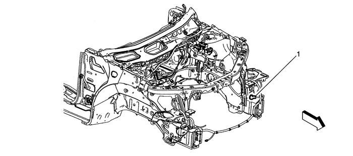
Route the hood switch wiring harness ground ring terminal to G101 ground location-(1).
Caution:Refer toFastener Caution.
Remove the G101 ground bolt, add the hood switch wiring harness ground ring terminalunder the existing ring terminal, and secure with original bolt and tighten to 9-Y (80-lb-in).Adjust the hood latch placement as needed for proper hood alignment.Reinstall all previous parts removed.If key cutting is required, cut the new keys using the existing key, if precut keyshave been ordered proceed to Programming Vehicle.Programming VehicleService Programming System (SPS)Note:For North America vehicles, the installation of accessory remote start requires BCMprogramming. This is done with a Service Programming System. The installer needs tocall the Techline Customer Support Center (1-800-828-6860). The Techline CustomerSupport Center will provide programming instructions and changes to the vehicles calibrationsettings. You must provide the vehicle identification number (VIN) ofthe vehicle to be programmed and the authorization code provided with the accessory,when calling.
For step-by-step control module programming instructions, please refer to the techlineinformation system (TIS) terminal.
Review the information below to ensure proper programming protocol.
Note:
DO NOT program a control module unless you are directed by a service procedure oryou are directed by a General Motors service bulletin. Programming a control moduleat any other time will not permanently correct a customers concern.It is essential that the TIS terminal, MDI, and/or Scan Tool, is equipped with thelatest software before performing service programming.Due to the time requirements of programming a controller, install SPS ProgrammingSupport Tool to maintain system voltage. Stable battery voltage is critical duringprogramming. Any fluctuation, spiking, over voltage or loss of voltage will interruptprogramming. If the above tool is not available, DO NOT connect a battery charger,connect a fully charged 12V jumper or booster pack disconnected from the AC voltagesupply.Some modules will require additional programming/setup events to be performed beforeor after programming.Some vehicles may require the use of a CANDi or MDI module for programming.Review the appropriate service information for these procedures.DTCs may set during programming. Clear DTCs after programming is complete.Clearing powertrain DTCs will set the Inspection/Maintenance (I/M) system status indicatorsto NO.Ensure the following conditions are met before programming a control module:
Vehicle system voltage:There is not a charging system concern. All charging system concerns must be repairedbefore programming a control module.Battery voltage is greater than 12-volts but less than 16-volts. The battery mustbe fully charged before programming the control module.Turn OFF or disable any system that may put a load on the vehicles battery, such asthe following components:Interior lightsExterior lights including daytime running lights (DRL)—Applying the parking brake,on most vehicles, disables the DRL systemHeating, ventilation, and air conditioning (HVAC) systemsEngine cooling fansRadio, etc.The ignition switch must be in the proper position. SPS prompts you to turn ON theignition, with the engine OFF. DO NOT change the position of the ignition switch duringthe programming procedure, unless instructed to do so.Make certain all tool connections are secure, including the following components andcircuits:Scan ToolThe RS-232 communication cable portThe connection at the data link connector (DLC)The voltage supply circuitsMDIThe USB, Ethernet or Wireless communication portThe connection at the data link connector (DLC)DO NOT disturb the tool harnesses while programming. If an interruption occurs duringthe programming procedure, programming failure or control module damage may occur.In the event of an interrupted or unsuccessful programming event, perform the followingsteps:
DO NOT turn the ignition OFF. Ensure that all control module and DLC connections aresecure and the TIS terminal operating software is up to date.Attempt to reprogram the control module.If the control module can still not be programmed, turn the ignition OFF for at leastone minute.Turn the ignition ON and attempt to reprogram the control module. The control moduleshould program.If the control module still cannot be programmed, replace the control module.After successfully programming the control module, ensure that all post programmingprocedures are performed; refer to Body Control Module Programming and Setup for theappropriate control module Programming and Setup document for any required procedures.
Body Control Module Programming and SetupThe body control module (BCM) must be programmed with the proper calibration software.The BCM stores and utilizes this information however if it is not properly configuredwith the correct calibration software, the BCM will not control all of the vehiclefeatures properly.
Ensure that the following conditions exist in order to prepare for BCM programming:
The battery is fully charged.The MDI data link connectors are secure.The scan tool is loaded with the most current software version.All disconnected modules and devices are reconnected securely.This entire procedure has been reviewed before proceeding.Do not reprogram the body control module unless directed by a service procedure ora service bulletin.
BCM Programming (Key Ignition System)To program and setup an existing or new replacement BCM, perform the following procedure:
With a scan tool, access the Service Programming System (SPS) and follow the on-screeninstructions.On the SPS Supported Controllers screen, select BCM Body Control Module - Programmingand follow the on-screen instructions.On the SPS Supported Controllers screen, select BCM Body Control Module - Setup andfollow the on-screen instructions.Note:When performing the Tire Pressure Monitor Sensor Learn during BCM setup, the TirePressure Monitor Diagnostic Tool must be used to activate each tire pressure sensor.
On the SPS Supported Controllers screen, select BCM Body Control Module - Configurationand follow the on-screen instructions (if applicable).On the SPS Supported Controllers screen, select IMMO Immobilizer Learn - Setup andfollow the on-screen instructions (only required if programming a replacement BCM).Check the driver information center display for additional messages regarding furthercalibration instructions. If there are no addition driver information center instructionspresent, programming is complete. #10-08-45-001D: Information for Electrical Ground Repair - Use New Replacement Fasteners with Conductive Finish - (Feb 14, 2013)
Subject:Information for Electrical Ground Repair — Use New Replacement Fasteners with ConductiveFinishModels: 2014 and Prior GM Passenger Cars and Trucks This bulletin is being revised to add th ...
 Body
Body
...
Other materials:
SIR Warning Secondary
Warning:This vehicle is equipped with a Supplemental InflatableRestraint (SIR) System. Failure to follow the correct procedurecould cause the following conditions:Air bag deploymentPersonal injuryUnnecessary SIR system repairsIn order to avoid the above conditions, observe the followingguidelines:Re ...
