Chevrolet Equinox Service Manual: #10-08-45-001D: Information for Electrical Ground Repair - Use New Replacement Fasteners with Conductive Finish - (Feb 14, 2013)
| Subject: | Information for Electrical Ground Repair — Use New Replacement Fasteners with ConductiveFinish |
|
| Models: | 2014 and Prior GM Passenger Cars and Trucks | |
This bulletin is being revised to add the 2013 and 2014 model years and remove theSaab Warranty Information section. Please discard Corporate Bulletin Number 10-08-45-001C(Section 08 – Body and Accessories).
Electrical Ground Repair OverviewProper electrical system function relies on secure, stable and corrosion-free electricalground connections. Loose, stripped, or corroded connections increase the possibilityof improper system function and loss of module communication. These conditions mayalso lead to unnecessary repairs and component replacement.
In general, electrical ground connections are accomplished using one, or a combinationof the following attachment methods:
Welded M6 stud and nutWelded M6 nut and boltWelded M8 nut and boltDetermine which attachment method is used and perform the appropriate or alternativerepair as described in this bulletin.
M6 Weld Stud ReplacementCaution:Use only the GM-approved replacement fasteners with conductive finish for electricalground repair.
Select a location adjacent the damaged or missing M6 ground stud having 20 mm (0.79in) clearance behind the panel surface and 20 mm (0.79 in) clearance surrounding theM6 conductive rivet stud flange.Using GM approved residue-free solvent or equivalent, remove any grease from the repairsite and allow to dry.Note:Ensure 20 mm (0.79 in) clearance is maintained behind the panel to be drilled.
Drill a 10 mm (0.40 in) diameter hole through the panel.
Remove paint and primer from the area surrounding the 10 mm (0.40 in) hole until baremetal is visible.

Important:The M6 conductive rivet stud as shown, can accommodate a panel thickness range of0.7-4.2 mm (0.03-0.17 in). If there are layers of sheet metal, they should be touchingwithout any air gaps to ensure a good ground.
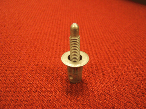
Select a M6 conductive rivet stud. Refer to the Parts Information section of thisbulletin.
Note:Use the GE-50317 rivet stud tool kit.
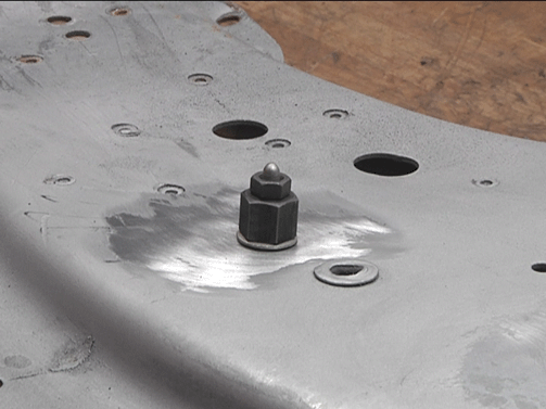
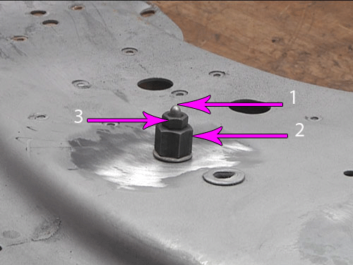
Place the M6 conductive rivet stud (1) in the 10 mm (0.40 in) hole. Assemble the rivetstud tool (2) with the groove and flare side facing the rivet stud, then the washerand the M6 nut (3).
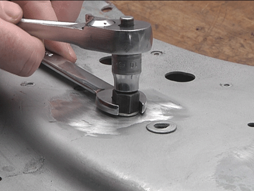
Using a wrench on the rivet stud tool, and a socket on the M6 nut, secure the M6 conductiverivet stud.Ensure the rivet stud is securely fastened, WITHOUT ANY detectable movement.Completely wrap the threads of the rivet stud with painters tape or equivalent.
Note:The rivet stud and surrounding panel area MUST BE properly refinished PRIOR to theinstallation of the ground wire terminal and conductive nut to maintain a secure,stable and corrosion-free electrical ground.
Refinish the repair area using an anti-corrosion primer. Refer to Anti-Corrosion Treatmentand Repair in SI.Allow the refinished repair area to cure sufficiently before removing the protectivematerial applied to the rivet stud threads.Remove the painters tape or equivalent from the rivet stud threads.Using GM approved residue-free solvent or equivalent, thoroughly clean the rivet studthreads to remove any adhesive and allow to dry.Using a small brush, apply Dielectric Lubricant GM P/N 12377900 (Canadian P/N 10953529)to the threads of the M6 conductive rivet stud.Note:Fretting corrosion is a build-up of insulating, oxidized wear debris that can formwhen there is a small motion between electrical contacts. The oxidized wear debriscan accumulate at the electrical contact points causing the electrical resistanceacross the connection to increase.
Carefully remove ANY corrosion or contamination that may be present on the electrical ground wire terminal.Install the electrical ground wire terminal to the rivet stud.Select a M6 conductive nut. Refer to the Parts Information section of this bulletin.Install the M6 conductive nut to the rivet stud and:Tighten
Tighten to 8 Y (71 lb in).Verify proper system operation.M6 Weld Nut
Caution:Use only the GM-approved replacement fasteners with conductive finish for electricalground repair.
If the M6 weld nut at the electrical ground location is damaged or stripped, a M7conductive self-threading bolt may be used to secure the ground wire terminal.Using GM approved residue-free solvent or equivalent, remove any grease from the surfacesurrounding the weld nut and allow to dry.Remove any loose metal particles from the damaged or stripped weld nut with a stiffbrush.Select a M7 conductive self-threading bolt. Refer to the Parts Information sectionof this bulletinUsing a small brush, apply Dielectric Lubricant GM P/N 12377900 (Canadian P/N 10953529)to the threads of the M7 conductive self-threading bolt.Note:Fretting corrosion is a build-up of insulating, oxidized wear debris that can formwhen there is a small motion between electrical contacts. The oxidized wear debriscan accumulate at the electrical contact points causing the electrical resistanceacross the connection to increase.
Carefully remove ANY corrosion or contamination that may be present on the electrical ground wire terminal.Install the electrical ground wire terminal to the M7 conductive self-threading bolt.Install the M7 conductive self-threading bolt and:Tighten
Tighten to 9 Y (80 lb in).Verify proper system operation.M6 Weld Nut Alternative Repair
Caution:Use only the GM-approved replacement fasteners with conductive finish for electricalground repair.
If the electrical ground location is accessible from both sides of the panel, a M6conductive bolt and a M6 conductive nut may be used to secure the electrical groundwire terminal. Refer to the Parts Information section of this bulletin.Select a location adjacent the damaged M6 weld nut having 20 mm (0.79 in) clearancebehind the panel surface and 20 mm (0.79 in) clearance surrounding the new electricalground site.Using GM approved residue-free solvent or equivalent, remove any grease from the surfacesurrounding the ground location and allow to dry.Note:Ensure 20 mm (0.79 in) clearance is maintained behind the panel to be drilled.
Drill a 8.5 mm (0.33 in) diameter hole through the panel.Remove paint and primer from the area surrounding the 8.5 mm (0.33 in) hole untilbare metal is visible.Select a M6 conductive bolt. Refer to the Parts Information section of this bulletin.Using a small brush, apply Dielectric Lubricant GM P/N 12377900 (Canadian P/N 10953529)to the threads of the M6 conductive bolt.Note:Fretting corrosion is a build-up of insulating, oxidized wear debris that can formwhen there is a small motion between electrical contacts. The oxidized wear debriscan accumulate at the electrical contact points causing the electrical resistanceacross the connection to increase.
Carefully remove ANY corrosion or contamination that may be present on the electrical ground wire terminal.Install the electrical ground wire terminal and the M6 conductive bolt to the groundlocation.Select a M6 conductive nut. Refer to the Parts Information section of this bulletin.Install the M6 conductive nut to the bolt and:Tighten
Tighten to 8 Y (71 lb in).
Note:The repair area MUST BE properly refinished to maintain a secure, stable and corrosion-freeelectrical ground.
Refinish the repair area using an anti-corrosion primer. Refer to Anti-Corrosion Treatmentand Repair in SI.Verify proper system operation.M8 Weld NutCaution:Use only the GM-approved replacement fasteners with conductive finish for electricalground repair.
If the M8 weld nut electrical ground location is accessible from both sides of thepanel, a M8 conductive bolt and a M8 conductive nut may be used to secure the electricalground wire terminal. Refer to the Parts Information section of this bulletin.Select a location adjacent the M8 weld nut having 20 mm (0.79 in) clearance behindthe panel surface and 20 mm (0.79 in) clearance surrounding the new electrical groundsite.Using GM approved residue-free solvent or equivalent, remove any grease from the surfacesurrounding the ground location and allow to dry.Note:Ensure 20 mm (0.79 in) clearance is maintained behind the panel to be drilled.
Drill a 10 mm (0.40 in) diameter hole through the panel.Remove paint and primer from the area surrounding the 10 mm (0.40 in) hole until baremetal is visible.Select a M8 conductive bolt. Refer to the Parts Information section of this bulletin.Using a small brush, apply Dielectric Lubricant GM P/N 12377900 (Canadian P/N 10953529)to the threads of the M8 conductive bolt.Note:Fretting corrosion is a build-up of insulating, oxidized wear debris that can formwhen there is a small motion between electrical contacts. The oxidized wear debriscan accumulate at the electrical contact points causing the electrical resistanceacross the connection to increase.
Carefully remove ANY corrosion or contamination that may be present on the electrical ground wire terminal.Install the electrical ground wire terminal and the M8 conductive bolt to the groundlocation.Select a M8 conductive nut. Refer to the Parts Information section of this bulletin.Install the M8 conductive nut to the bolt and:Tighten
Tighten to 22 Y (16 lb ft).
Note:The repair area MUST BE properly refinished to maintain a secure, stable and corrosion-freeelectrical ground.
Refinish the repair area using an anti-corrosion primer. Refer to Anti-Corrosion Treatmentand Repair in SI.Verify proper system operation.M8 Weld Nut Alternative RepairCaution:Use only the GM-approved replacement fasteners with conductive finish for electricalground repair.
If the M8 weld nut electrical ground location is not accessible from both sides ofthe panel, a M6 conductive rivet stud and a M6 conductive nut may be used to securethe electrical ground wire terminal.Select a location adjacent the damaged M8 weld nut having 20 mm (0.79 in) clearancebehind the panel surface and 20 mm (0.79 in) clearance surrounding the M6 conductiverivet stud flange.Using GM approved residue-free solvent or equivalent, remove any grease from the repairsite and allow to dry.Note:Ensure 20 mm (0.79 in) clearance is maintained behind the panel to be drilled.
Drill a 10 mm (0.40 in) diameter hole through the panel.
Remove paint and primer from the area surrounding the 10 mm (0.40 in) until bare metalis visible.

Important:The M6 conductive rivet stud as shown, can accommodate a panel thickness range of0.7-4.2 mm (0.03-0.17 in). If there are layers of sheet metal, they should be touchingwithout any air gaps to ensure a good ground.
Select a M6 conductive rivet stud. Refer to the Parts Information section of thisbulletin.
Note:Use the GE-50317 rivet stud tool kit.
Place the M6 conductive rivet stud (1) in the 10 mm (0.40 in) hole. Assemble the rivetstud tool (2) with the groove and flare side facing the rivet stud, then the washerand the M6 nut (3).
Using a wrench on the rivet stud tool, and a socket on the M6 nut, secure the M6 conductiverivet stud.Ensure the new rivet stud is securely fastened, WITHOUT ANY detectable movement.Completely wrap the threads of the rivet stud with painters tape or equivalent.
Note:The rivet stud and surrounding panel area MUST BE properly refinished PRIOR tothe installation of the electrical ground wire terminal and conductive nut to maintaina secure, stable and corrosion-free electrical ground.
Refinish the repair area using an anti-corrosion primer. Refer to Anti-Corrosion Treatmentand Repair in SI.Allow the refinished repair area to cure sufficiently before removing the protectivematerial applied to the rivet stud threads.Remove the painters tape or equivalent from the rivet stud threads.Using GM approved residue-free solvent or equivalent, thoroughly clean the rivet studthreads to remove any adhesive and allow to dry.Using a small brush, apply Dielectric Lubricant GM P/N 12377900 (Canadian P/N 10953529)to the threads of the M6 conductive rivet stud.Note:Fretting corrosion is a build-up of insulating, oxidized wear debris that can formwhen there is a small motion between electrical contacts. The oxidized wear debriscan accumulate at the electrical contact points causing the electrical resistanceacross the connection to increase.
Carefully remove ANY corrosion or contamination that may be present on the electrical ground wire terminal.Install the electrical ground wire terminal to the M6 conductive rivet stud.Select a M6 conductive nut. Refer to the Parts Information section of this bulletin.Install the M6 conductive nut to the rivet stud and:Tighten
Tighten to 8 Y (71 lb in)Verify proper system operation.Parts Information
11561645 | M6 NUT |
11570340 | M6 RIVET STUD |
11588564 | M8 BOLT |
11609412 | M8 NUT |
11609538 | M7 BOLT (SELF-THREADING) |
11609669 | M6 BOLT |
GM P/N 12377900 (Canada P/N 10953529) | DIELECTRIC LUBRICANT |
For vehicles repaired under warranty, use:
N6620* MY2009 and Prior | Power and Grounds Distribution Wiring and/or Connector Repair or Replacement | Use Published Labor Operation Time |
B9699* MY2010-2014 | Body Ground Stud or Nut Repair or Replacement | |
*YOU MUST document the affected ground location on the repair order. Note:Any additional time for component R&R to gain access or for repair time greater than0.5 hours must be submitted as Other Labor Hours and requires appropriate authorizationand service management approval. | ||
GM bulletins are intended for use by professional technicians,NOT a "do-it-yourselfer". They are written to inform thesetechnicians of conditions that may occur on some vehicles, or toprovide information that could assist in the proper service of avehicle. Properly trained technicians have the equipment,tools, safety instructions, and know-how to do a job properly andsafely. If a condition is described, DO NOT assume that thebulletin applies to your vehicle, or that your vehicle will havethat condition. See your GM dealer for information on whetheryour vehicle may benefit from the information. |
| WE SUPPORT VOLUNTARY TECHNICIAN CERTIFICATION |
 Front Fog Lamp Package Installation
Installation Instructions Part Number23206778Kit ContentsQtyDescription1Left Fog Lamp Assembly1Right Fog Lamp Assembly1Left Fog Lamp Bezel1Right Fog Lamp Bezel1Steering Column Switch6Tie Straps1Fog La ...
 Remote Control Door Lock, Theft Deterrent, and Remote Start Transmitter Package Installation
Table 1: Kit ContentsTable 2: Replacement Key DescriptionInstallation Instructions Part Number20981984Kit ContentsQtyDescription1Hood Latch P/N 20941413 (MY10-11 Kit P/N 20981996)1Hood Latch P/N 22787 ...
Other materials:
Adhesives, Fluids, Lubricants, and Sealers Driveshafts Propeller Shaft Assembly
Adhesives, Fluids, Lubricants, and SealersApplicationType of MaterialGM Part NumberCanadian Part NumberCenter Bearing to Vehicle BoltsThreadlocker8902129710953488Front Propeller Shaft CVJ BoltsThreadlocker8902129710953488Propeller Shaft Rear Attaching BoltsThreadlocker8902129710953488 ...


