Chevrolet Equinox Service Manual: Rear Output Drive Housing Cleaning and Inspection Automatic Transmission Unit

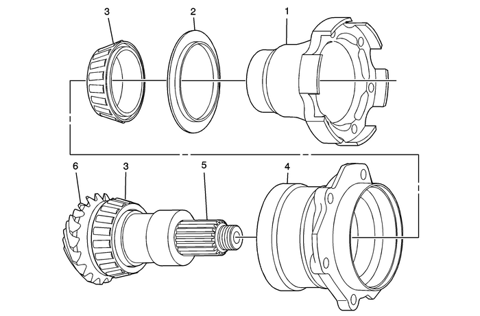
| Preliminary ProceduresClean all components in cleaning solvent and air dry.The transfer case internal components are not to be serviced. If internal componentsother than seals are damaged, the transfer case must be replaced. | |
1 | Transfer Case Rear Output Shaft Flange Note: Replace if flange, threaded holes, or splines are damaged.Inspect sealing surface for corrosion, excessive wear, or damage. |
2 | Transfer Case Rear Output Shaft Oil Slinger Note:Replace the slinger if damaged, cracked, loose, or distorted. |
3 | Transfer Case Rear Output Shaft Bearing Assembly Note:Inspect bearings for roughness, spalling, or pitting. |
4 | Transfer Case Rear Output Shaft Housing Note: Inspect for cracks, broken areas, or other damage.Inspect bearing races for roughness, brinelling, or pitting.Inspect the O-ring channel for porosity or damage.Scratches or nicks in other areas may be repaired with light sanding. |
5 | Transfer Case Rear Output Shaft Splines Note:Inspect for damage and press fit to flange. |
6 | Transfer Case Rear Output Shaft Note:Inspect for pitting, excessive wear, or damage. |
 Reaction Carrier Hub and 2-6 Clutch Plate Removal Automatic Transmission Unit
Reaction Carrier Hub and 2-6 Clutch Plate RemovalCalloutComponent Name12–6 Clutch Hub Thrust Bearing AssemblyNote:The 2–6 clutch hub thrust bearing assembly may be stuck to the reaction carrier hu ...
 Control Valve Body Cover Replacement Automatic Transmission Unit Control Valve Body
Removal ProcedureDisconnect the negative battery cable. Refer toBattery Negative Cable Disconnection and Connection.Disconnect the radiator outlet hose from the radiator. RefertoRadiator Outlet Hose R ...
Other materials:
Rear Wheel Drive Shaft Inner Joint and Boot Replacement Wheels
Special ToolsJ-35910Drive Axle Boot Clamp PliersNote:The inner Constant Velocity Joint is not serviced separately.If the CV joint is found to have excessive wear or damaged, replacethe wheel drive shaft as an assembly.Disassemble ProcedureRemove the wheel drive shaft. Refer toRear Wheel Drive Shaft ...
