Chevrolet Equinox Service Manual: Master Cylinder Reservoir Replacement Hydraulic Brakes Brake Fluid Reservoir
Removal Procedure
Warning:Refer toBrake Fluid Irritant Warning.
Caution:Refer toBrake Fluid Effects on Paint and Electrical Components Caution.
Using a suitable tool, remove the brake fluid from the brakemaster cylinder reservoir.Discard the brake fluid into an approved container.
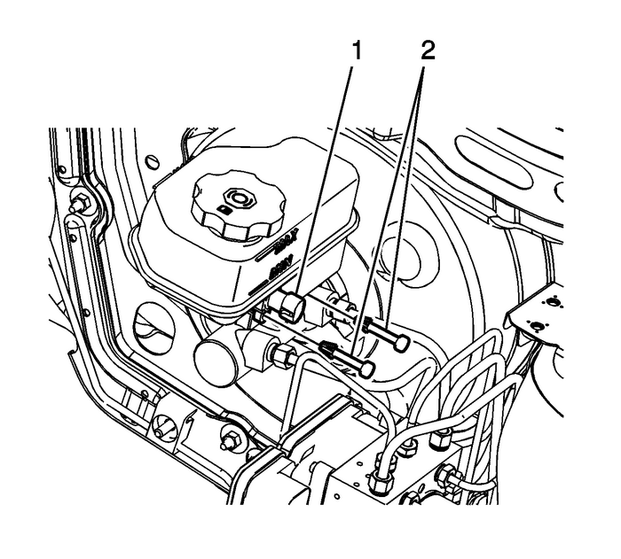
Disconnect the master cylinder fluid level sensor electricalconnector-(1).Remove and discard the master cylinder reservoir retainingpins-(2)-by compressing the lockingtabs.

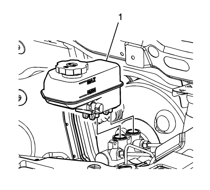
Carefully remove the master cylinderreservoir-(1)-by pulling the reservoirstraight up.

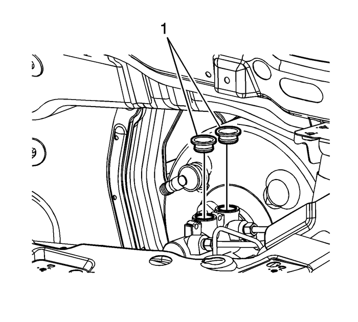
Remove the master cylinder reservoirseals-(1).Installation ProcedureLubricate the master cylinder reservoir seals with GMapproved brake fluid from a clean, sealed brake fluidcontainer.

Install the master cylinder reservoirseals-(1).

Install the master cylinderreservoir-(1)-to the master cylinder.Ensure the master cylinder reservoir bayonets are fullyseated in the master cylinder.

Connect the master cylinder fluid level sensor electricalconnector-(1).Install new master cylinder reservoir retainingpins-(2).Ensure the retaining pins are fully seated and the lockingtabs are fully deployed.Fill the master cylinder reservoir to the proper level. RefertoMaster Cylinder Reservoir Filling.Observe the brake pedal feel after filling the mastercylinder reservoir. If the pedal feels spongy, bleed the hydraulicbrake system. Refer toHydraulic Brake System Bleeding.
 Power Vacuum Brake Booster Replacement Hydraulic Brakes Brake Booster
Removal ProcedureWarning:Refer toBrake Fluid Irritant Warning.Caution:Refer toBrake Fluid Effects on Paint and Electrical Components Caution.Remove the vacuum brake booster vacuum sensor and hose from ...
 Power Brake Booster Vacuum Sensor Replacement (LEA) Hydraulic Brakes Brake Booster
Removal ProcedureWith the engine OFF, apply and release the brake pedalseveral times until the brake pedal becomes firm to deplete thepower vacuum brake booster vacuum reserve.Disconnect the power bra ...
Other materials:
Fastener Tightening Specifications - Propeller Shaft Assembly Driveshafts Propeller Shaft Assembly
Fastener Tightening SpecificationsApplicationSpecificationMetricEnglishCenter Bearing-to-Vehicle Underbody Bolts25-Y19-lb-ftPropeller Shaft-to-Rear Differential Flange Bolts50-Y37-lb-ftPropeller Shaft-to-Transfer Case Flange Bolts35-Y25-lb-ft ...
