Chevrolet Equinox Service Manual: Manual Shift Detent Lever with Shaft Position Switch Assembly Replacement Automatic Transmission Unit
Special ToolsDT-41229 Manual Shaft Pin InstallerDT-48550 Detent Lever Pin Remover
For equivalent regional tools, refer toSpecial Tools.
Removal Procedure
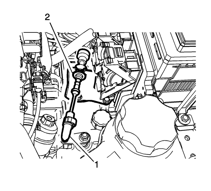
Disconnect the transmission range selector lever cable terminal-(1) from the transmissionmanual shift lever pin.Remove the control valve body cover. Refer toControl Valve Body Cover Replacement.Remove the control valve body. Refer toControl Valve Body Replacement.

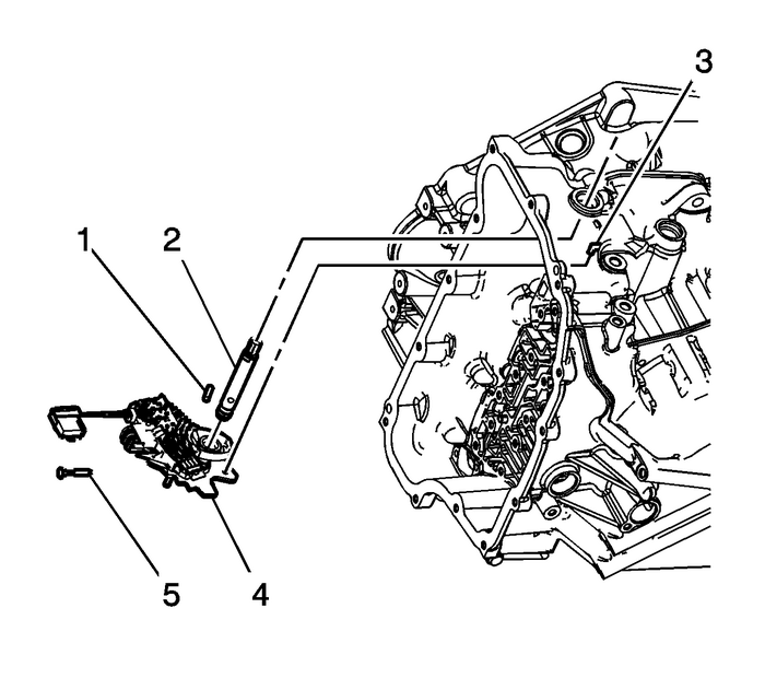
Remove the manual shaft detent lever hub pin-(1) using DT-48550 remover.Remove the manual shift shaft pin-(5) using diagonal pliers or equivalent tool. Discardthe pin.Remove the manual shaft-(2).
Note:
Disconnect the actuator rod-(3) from the detent lever assembly. Do not remove theactuator rod from the transmission case.Do not pull the park actuator rod end out beyond the machined oil passage surfacein the case. A no park condition will exist if the park pawl actuator assembly ispulled out of the transmission too far and the actuator rod disengages from the parkpawl. The transmission assembly will require disassembly to reinstall the actuatorrod over the park pawl.Remove the manual shaft detent (w/shift position switch) lever assembly-(4).Installation Procedure
Note:Connect the actuator rod-(3) to the detent lever assembly.
Install the manual shaft detent (w/shift position switch) lever assembly-(4).Note:Lubricate the shaft with automatic transmission fluid to prevent damage to the manualshift shaft seal during installation.
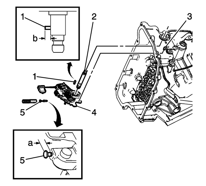
Install the manual shaft-(2).Install the manual shaft detent lever hub pin-(1) using DT-41229 Installer.Specification
Install the Manual Shaft Detent Lever Hub Pin to height of (b) 7.9-mm (0.38-in).
Caution:Use the manual shaft pin installer to install the pin at thecorrect height in order to properly secure the manual shaft. If youinstall the pin too deep, the case bore may crack.
Install the NEW manual shift shaft pin-(5) using DT-41229 Installer. Use a NEW pin to ensure proper engagement with the case.Specification
Inspect pin installed height is within (a) 7.2–8.2-mm (0.28–0.32-in).Install the control valve body. Refer toControl Valve Body Replacement.Install the control valve body cover. Refer toControl Valve Body Cover Replacement.

Connect the transmission range selector lever cable terminal-(1) from the transmissionmanual shift lever pin.
 Case Porosity Repair Automatic Transmission Unit
Some external leaks are caused by case porosity innon-pressurized areas.Thoroughly clean the area to be repaired with a cleaningsolvent. Air dry the area.Warning:Epoxy adhesive may cause skin irritati ...
 Engine Flywheel Installation Flywheel/Flexplate
Special ToolsEN-38122-ACrankshaft Balancer HolderEN-43653Flywheel Holding ToolEN-45059Angle MeterFor equivalent regional tools, refer toSpecial Tools.Install the flywheel.Install NEW bolts.Caution:Ref ...
Other materials:
Jump Starting
Jump Starting - North America
For more information about the
vehicle battery, see Battery - North
America.
If the battery has run down, try to
use another vehicle and some
jumper cables to start your vehicle.
Be sure to use the following steps to
do it safely.
Warning
WARNING: ...
