Chevrolet Equinox Service Manual: Low and Reverse and 1-2-3-4 Clutch Housing, and 1-2-3-4 Clutch Plate Installation (6T40/45/50) Automatic Transmission Unit Automatic Clutches

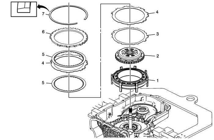
1 | Low and Reverse and 1–2–3–4 Clutch Housing Note:The longer legs face the bottom of the case and the oil passages face the valve bodyend of the case. |
2 | Output Sun Gear Assembly |
3 | 1–2–3–4 Clutch Waved Plate Note: Align the single pair of tabs with the bottom valve body end of the case.Ensure the correct waved plate is being installed. The 1–2–3–4 clutch and low andreverse clutch waved plates are visually similar, however the low and reverse clutchwaved plate is thicker. |
4 | 1–2–3–4 Clutch Plate-(Qty:-2) |
5 | 1–2–3–4 Clutch Plate Assembly-(Qty:-2) |
6 | 1–2–3–4 Clutch Backing Plate Note:Align the single skinny tab with the case spline facing the top of the case. |
7 | 1–2–3–4 Clutch Backing Plate Retainer Ring Warning:The retainer is under tension. Use care when removing orinstalling the retainer. Personal injury could result. Caution:Use caution during removal or installation of the retainerring to avoid damage to the case machined surface in the park pawlarea. Burrs or raised edges on the case machined surface can causethe park pawl to bind and prohibit it from engaging the parkgear. Note: Install the retainer with the taper facing away from the backing plate.Align the retainer opening with the largest gap in the case splines toward the bottomof the case.Install one end of the retainer into the retainer ring groove. Use DT-28585 snap ring remover and work the retainer into the case groove. Use a screwdriver to hold the retaineraway from the case while pushing down on the retainer with DT-28585 snap ring remover.Special Tool DT-28585 Snap Ring Remover or equivalent For equivalent regional tools, refer toSpecial Tools. |
 Solenoid Valve Pressure (Gen 2) Automatic Transmission Unit
Line PC Solenoid Valve PressureRequested Pressure (kPa)Actual PressureMetricEnglishNone172–379-kPa25–55-psi200662–869-kPa96–126-psi4001145–1351-kPa166–196-psi6001634–1841-kPa237–267-ps ...
 Low and Reverse and 1-2-3-4 Clutch Housing Cleaning and Inspection Automatic Transmission Unit Automatic Clutches
Low and Reverse and 1-2-3-4 Clutch Housing Cleaning and InspectionCalloutComponent NameCaution:After cleaning the transmission components, allow to air dry.Do not use cloth or paper towels in order to ...
Other materials:
Rear Wheel Drive Module Clutch Housing Replacement Wheels
Rear Wheel Drive Module Clutch Housing ReplacementCalloutComponent NamePreliminary ProceduresRaise the vehicle. Refer toLifting and Jacking the Vehicle.Remove the propeller shaft from the differential clutch drumassembly. Refer toPropeller Shaft Replacement.1Electrical Clutch Control Connector2Retai ...
