Chevrolet Equinox Service Manual: Instrument Panel Upper Trim Panel Replacement Consoles Center Console
Chevrolet Equinox Service Manual / Body / Body Interior / Instrument Panel Upper Trim Panel Replacement Consoles Center Console

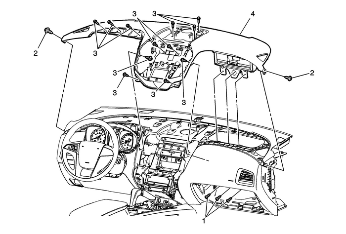
| Preliminary ProceduresDisable the SIR system. Refer toSIR Disabling and Enabling.Remove the instrument panel accessory trim plate. Refer toInstrument Panel Accessory Trim Plate ReplacementRemove the instrument panel cluster trim plate bezel. RefertoInstrument Panel Cluster Trim Plate Bezel Replacement.Remove the left and right instrument panel side trim panels.Refer toInstrument Panel Side Trim Panel Replacement.Remove the instrument panel compartment door assembly. RefertoInstrument Panel Compartment Door Replacement.Remove the instrument panel center compartment, if equipped.Refer toInstrument Panel Center Compartment ReplacementRemove the radio front center speaker. Refer toRadio Front Center Speaker Replacement.Remove the radio control assembly. Refer toRadio Control Assembly Replacement.Remove the right and left instrument panel center airoutlets. Refer toInstrument Panel Center Air Outlet Replacement.Remove the instrument panel lower extension accessory bezel.Refer toInstrument Panel Lower Extension Accessory Bezel Replacement.Remove the instrument panel upper center trim panel, ifequipped. Refer toInstrument Panel Upper Center Trim Panel ReplacementRemove the radio, video, audio disc player, and navigationalinformation display, if equipped. Refer toRadio, Video, and Audio Player and Navigation Information Display Replacement.Remove the instrument panel center compartment bracket, ifequipped. Refer toInstrument Panel Center Compartment Bracket Replacement. | |
1 | Instrument Panel Inflatable Restraint Fasteners(Qty:-3) Caution:Refer toFastener Caution. Tighten9-Y(80-lb-in) |
2 | Instrument Panel Upper Trim Panel Screws(Qty:-4) Tighten2.5-Y(22-lb-in) |
3 | Instrument Panel Upper Trim Panel Bolts(Qty:-10) Tighten2.5-Y(22-lb-in) |
4 | Instrument Panel Upper Trim Panel Assembly ProceduresNote location and routing of the instrument panel wiringharness prior to removing the instrument panel upper trim panel toensure proper reinstallation.When replacing the instrument panel upper trim panelassembly, transfer all necessary components. |
 Instrument Panel Upper Center Trim Panel Replacement (Terrain) Consoles Center Console
Instrument Panel Upper Center Trim Panel ReplacementCalloutComponent Name1Instrument Panel Upper Center Trim Panel AssemblyProcedureApply firm inward pressure at the top center of the radiocontrol ass ...
 Instrument Panel Upper Trim Panel Replacement (Terrain) Consoles Center Console
Instrument Panel Upper Trim Panel ReplacementCalloutComponent NamePreliminary ProceduresDisable the SIR system. Refer toSIR Disabling and Enabling.Remove the left and right side window defroster outle ...
Other materials:
Steering Linkage Outer Tie Rod Replacement Tie Rods and Linkage
Steering Linkage Outer Tie Rod ReplacementCalloutComponent NamePreliminary ProcedureRemove the front tire and wheel assembly. Refer toTire and Wheel Removal and Installation.1Steering Linkage Outer Tie Rod NutCaution:Refer toFastener Caution.ProcedureUse a wrench in order to hold the stud and preven ...
© 2017-2026 Copyright www.cequinox.com

