Chevrolet Equinox Service Manual: Instrument Carrier Replacement (Terrain) Consoles Center Console
Removal ProcedureRemove the instrument panel lower trim pad retainer assembly.Refer toLower Trim Pad Retainer Replacement.Remove the left and right air distributor outer ducts. RefertoAir Distributor Outer Duct Replacement - Left SideandAir Distributor Outer Duct Replacement - Right Side.Remove the center air outlet duct. Refer toInstrument Panel Center Air Outlet Duct Replacement.Remove the left and right side window defogger outlet ducts.Refer toSide Window Defogger Outlet Duct Replacement - Left SideandSide Window Defogger Outlet Duct Replacement - Right Side.Remove the windshield defroster duct. Refer toWindshield Defroster Duct Replacement.Remove the communication interface module. Refer toCommunication Interface Module Replacement.Remove the radio speaker amplifier. Refer toRadio Speaker Amplifier Replacement.Remove the body control module. Refer toBody Control Module Replacement.Remove the instrument wiring harness junction block from itsbracket. Refer toInstrument Panel Wiring Harness Junction Block Replacement.Disconnect the ground wire connected to the instrument wiringharness junction block bracket.
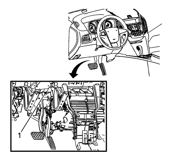
Remove the bolt-(1) securing the brake pedalbracket to the instrument panel carrier assembly.
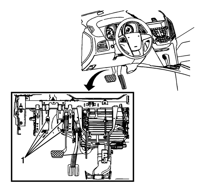
Remove the nuts-(1) securing the instrument panelcarrier assembly to the mod plate.
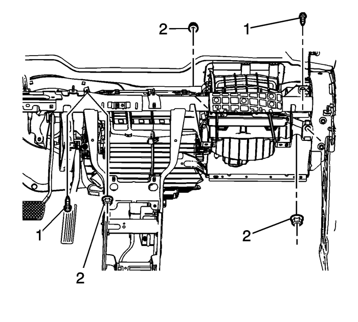
Remove the bolts-(1) securing the HVAC module tothe instrument panel carrier assembly.Remove the nuts-(2) securing the HVAC module tothe instrument panel carrier assembly.
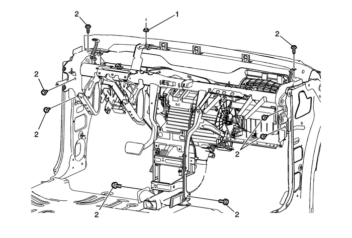
Remove the nut-(1) securing the instrument panelcarrier assembly to the vehicle body.Remove the bolts-(2) securing the instrument panelcarrier assembly to the vehicle body.Note the location and routing of the instrument panel wiringharness to ensure proper reinstallation.Disconnect the instrument panel wiring harness fasteners fromthe instrument panel carrier assembly and route the wiring harnessout of the way.Adequately support the HVAC module in order to preventdamage.
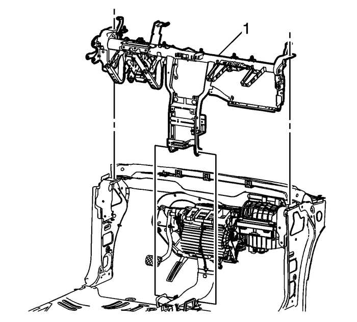
Remove the instrument panel carrier from the vehicle.If replacing the instrument panel carrier assembly, transferall necessary components to the new carrier assembly.Installation Procedure

Position the instrument panel carrier in the vehicle.Reposition the instrument panel wiring harness as was notedin the removal procedure and reattach the wiring harness to theinstrument panel carrier assembly.

Loosely install the bolts-(1) securing the HVACmodule to the instrument panel carrier assembly.Loosely install the nuts-(2) securing the HVACmodule to the instrument panel carrier assembly.

Loosely install the bolts-(2) securing theinstrument panel carrier assembly to the vehicle body.Loosely install the nut-(1) securing theinstrument panel carrier assembly to the vehicle body.

Loosely install the nuts-(1) securing theinstrument panel carrier assembly to the mod plate.

Loosely install the bolt-(1) securing the brakepedal bracket to the instrument panel carrier assembly.
Caution:Refer toFastener Caution.
Tighten the bolts and the nuts securing the HVAC module tothe instrument panel carrier assembly to6-Y(53-lb-in).Tighten the bolt securing the brake pedal bracket to theinstrument panel carrier assembly to22-Y(16-lb-ft).Tighten the nuts securing the instrument panel carrierassembly to the mod plate to22-Y(16-lb-ft).Tighten the bolts and the nut securing the instrument panelcarrier assembly to the vehicle body to22-Y(16-lb-ft).Connect the ground wire to the instrument wiring harnessjunction block bracket.Install the instrument wiring harness junction block into itsbracket. Refer toInstrument Panel Wiring Harness Junction Block Replacement.Install the body control module. Refer toBody Control Module Replacement.Install the radio speaker amplifier. Refer toRadio Speaker Amplifier Replacement.Install the communication interface module. Refer toCommunication Interface Module Replacement.Install the windshield defroster duct. Refer toWindshield Defroster Duct Replacement.Install the left and right side window defogger outlet ducts.Refer toSide Window Defogger Outlet Duct Replacement - Left SideandSide Window Defogger Outlet Duct Replacement - Right Side.Install the center air outlet duct. Refer toInstrument Panel Center Air Outlet Duct Replacement.Install the left and right air distributor outer ducts. RefertoAir Distributor Outer Duct Replacement - Left SideandAir Distributor Outer Duct Replacement - Right Side.Install the instrument panel lower trim pad retainerassembly. Refer toLower Trim Pad Retainer Replacement.Refer toControl Module Referencesfor programming and setupinformation for the body control module , communication interfacemodule, drivers information display, and the instrumentcluster. Rear Side Door Trim Panel Replacement Trim Panels/Welts
Rear Side Door Trim Panel ReplacementCalloutComponent NamePreliminary ProcedureRemove the rear door accessory switch mount plate. Refer toRear Side Door Accessory Switch Mount Plate Replacement.1Rear ...
 Roof Rail Front Assist Handle Replacement Grab Handles
Roof Rail Front Assist Handle ReplacementCalloutComponent Name1Roof Rail Front Assist Handle Fastener(Qty:-2)Caution:Refer toFastener Caution.ProcedureFold the assist handle downward and hold.Use a sm ...
Other materials:
Radiator Cleaning Engine Cooling Radiator
Warning:NEVER spray water on a hot heat exchanger. The resultingsteam could cause personal injury.Caution:The heat exchanger fins are necessary for good heat transfer.Do not brush the fins. This may cause damage to the fins, reducingheat transfer.Note:Remove bugs, leaves, dirt and other debris by bl ...
