Chevrolet Equinox Service Manual: Fuel Pressure Sensor Replacement Engine Control Engine Control Sensors
Removal ProcedureRelieve the fuel system pressure. Refer toFuel Pressure Relief.

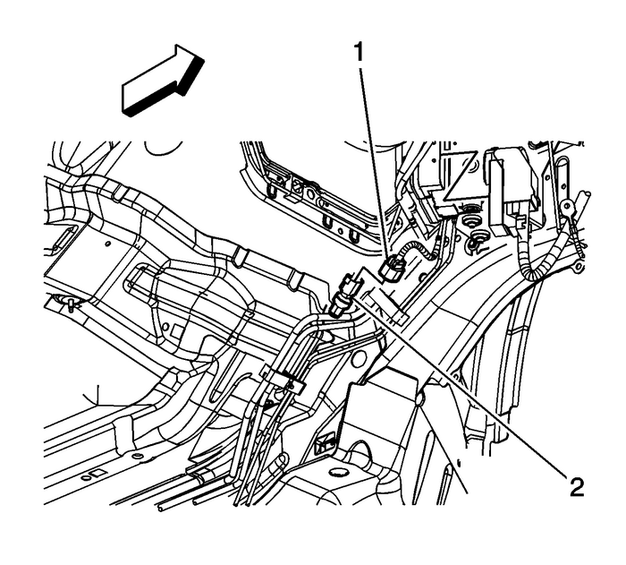
Raise and suitably support the vehicle. Refer toLifting and Jacking the Vehicle.Disconnect the body wiring harness electricalconnector-(1) from the fuel pressuresensor-(2).

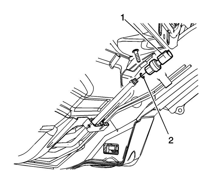
Wrap a shop towel around the fuel pressure sensor fitting inorder to absorb any fuel that may leak out.Remove the fuel pressure sensor (1) from the fuelline.Remove and discard the fuel pressure sensor O-ringseal-(2).Installation Procedure

Lubricate a NEW fuel pressure sensor O-ring seal with cleanengine oil.Install the NEW fuel pressure sensor O-ringseal-(2) onto the fuel line fitting.
Caution:Refer toFastener Caution.
Install the fuel pressure sensor (1) to the fuel line.Tighten the sensor to15-Y(11-lb-ft).
Connect the body wiring harness electrical connector (1) tothe fuel pressure sensor-(2).Lower the vehicle.Use the following procedure in order to inspect forleaks:Turn the ignition ON, with the engine OFF, for 2seconds.Turn the ignition OFF for 10 seconds.Turn the ignition ON, with the engine OFF.Inspect for fuel leaks.
 Spark Plug Replacement Engine Control
Removal ProcedureCaution:This engine has aluminum cylinder heads. Do not remove thespark plugs from a hot engine, allow it to cool first. Removing thespark plugs from a hot engine may cause spark plug ...
 Spark Plug Replacement Engine Control
Removal ProcedureRemove the ignition coil(s). Refer toIgnition Coil Replacement - Bank 1and/orIgnition Coil Replacement - Bank 2.Warning:Refer toSafety Glasses and Compressed Air Warning.Caution:Clean ...
Other materials:
Positive Crankcase Ventilation Tube Replacement - Front Emissions PCV
..Positive Crankcase Ventilation Tube Replacement - FrontCalloutComponent NamePreliminary ProcedureRemove the intake manifold cover. Refer toIntake Manifold Cover Replacement.1Positive Crankcase Ventilation Tube ...
