Chevrolet Equinox Service Manual: Engine Replacement
Special ToolsBO-38185Hose Clamp PliersCH-24319-BSteering Linkage and Tie Rod PullerJ-43828Ball Joint SeparatorJ-44015Steering Linkage Installer
For equivalent regional tools, refer toSpecial Tools.
Removal ProcedureDisconnect the negative battery cable. Refer toBattery Negative Cable Disconnection and Connection.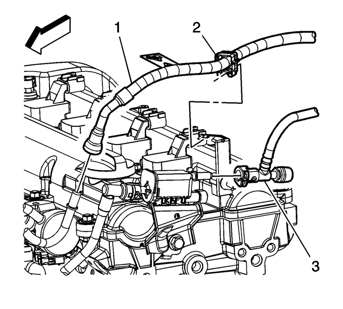
Relieve the fuel system pressure. Refer toFuel Pressure Relief.Remove the air cleaner outlet duct. Refer toAir Cleaner Outlet Duct Replacement.Remove the air cleaner assembly. Refer toAir Cleaner Assembly Replacement.Disconnect the fuel feed pipe-(1) quick connectfitting at the fuel rail. Refer toMetal Collar Quick Connect Fitting Service.Disconnect the evaporative emission (EVAP)line-(3) quick connect fitting from the EVAP purgesolenoid. Refer toPlastic Collar Quick Connect Fitting Service.Remove the fuel feed pipe clip-(2) from the fuelline bracket.Remove the intake manifold. Refer toIntake Manifold Replacement.Remove the engine control module cover and disconnectelectrical connectors.Remove the accessory wiring junction block, disconnect andreposition wiring harness to engine. Refer toAccessory Wiring Junction Block Replacement.Remove the exhaust manifold heat shield. Refer toExhaust Manifold Heat Shield Replacement.Remove the oxygen sensors. Refer toHeated Oxygen Sensor Replacement - Sensor 1andHeated Oxygen Sensor Replacement - Sensor 2.Raise and support the vehicle. Refer toLifting and Jacking the Vehicle.Remove the front wheels and tires. Refer toTire and Wheel Removal and Installation.Drain the cooling system. Refer toCooling System Draining and Filling.Drain the engine oil. Refer toEngine Oil and Oil Filter Replacement.Lower the vehicle.
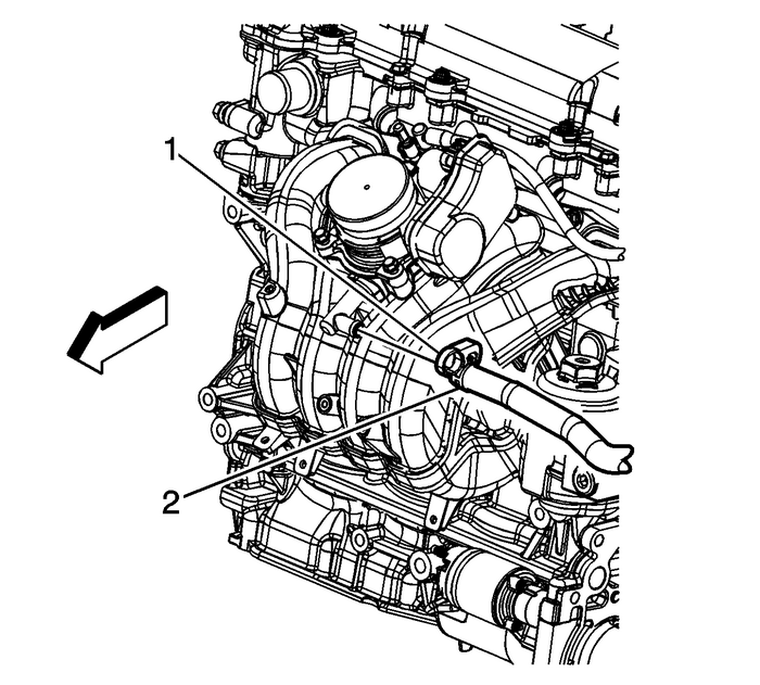
Reposition the vacuum brake booster hose clamp-(1)at the intake manifold.Remove the vacuum brake booster hose-(2) from theintake manifold. Reposition the brake booster hose out of theway.
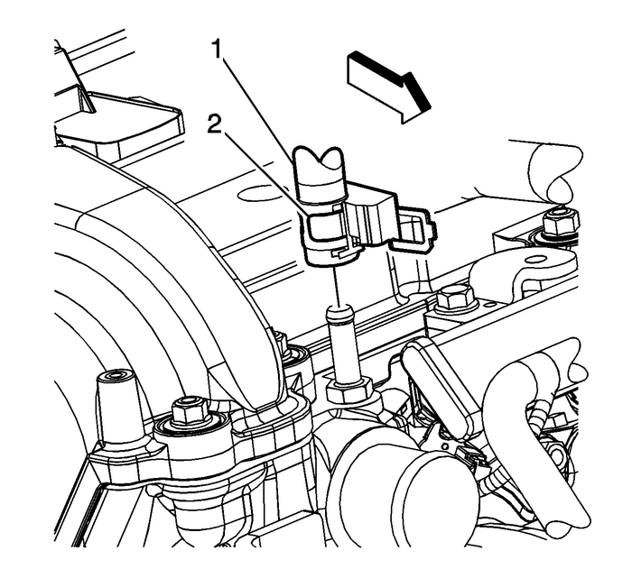
Remove the coolant recovery inlet hose clamp-(2)at the cylinder head.Remove the coolant recovery inlet pipe from the fuel pumpcover.Remove the coolant recovery inlet hose-(1) fromthe cylinder head. Reposition the hose/pipe out of the way.
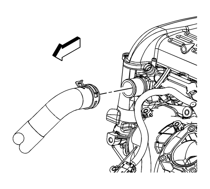
Reposition the radiator inlet hose clamp using theBO-38185pliers.Remove the radiator inlet hose from the cylinder head.Remove the radiator outlet hose. Refer toRadiator Outlet Hose Replacement.
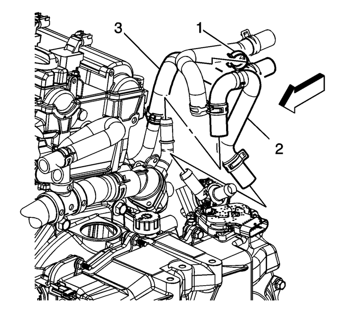
Reposition the heater inlet hose clamp at the thermostathousing.Remove the heater inlet hose from the thermostathousing.Remove the heater outlet hose clamp and hose at thermostathousing.Reposition the coolant recovery reservoir/heater inlethose-(2) clamp at the thermostat housing.Remove the coolant recovery reservoir/heater inlethose-(2) from the thermostat housing.Raise and support the vehicle. Refer toLifting and Jacking the Vehicle.Disconnect the engine wiring harness electrical connectorfrom the air conditioning (A/C) compressor.
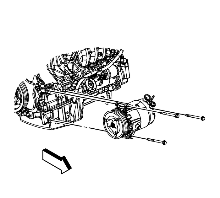
Unbolt the A/C compressor and reposition and secure out ofthe way.Remove the negative battery cable lead from the transaxlestud. Reposition the negative battery cable out of the way.Remove the starter. Refer toStarter Replacement.Lower the vehicle.
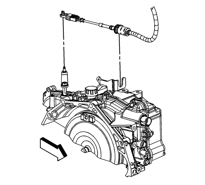
Remove the transaxle shift cable from the range selectlever.Release the shift control cable retaining clip and remove thecable from the shift control cable bracket.
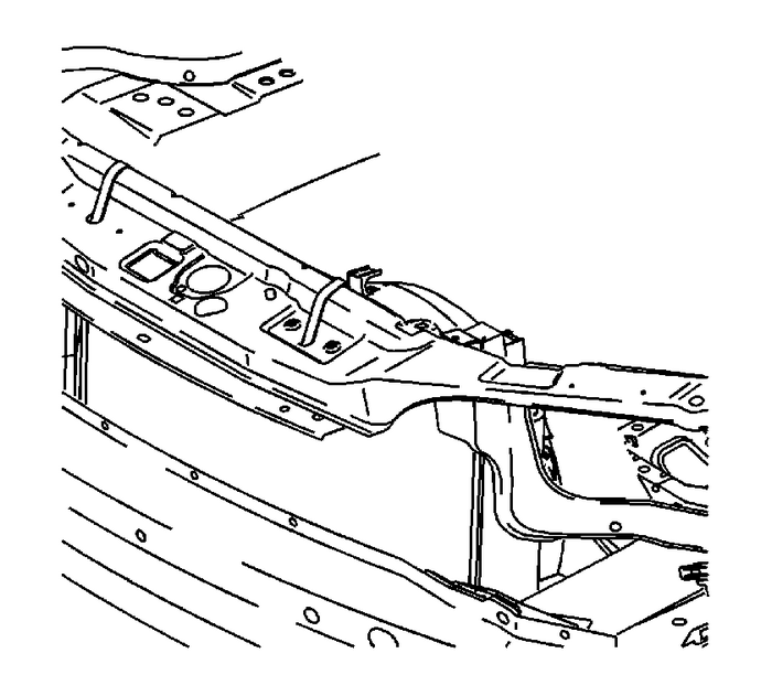
Note:The radiator/condenser/fan assembly will stay in the vehicleduring engine removal.
Using long tie straps, secure the radiator/condenser/fanassembly to the radiator support.Raise the vehicle.Remove the left engine splash shield. Refer toEngine Splash Shield Replacement - Left Side.Note:A piece of hardwood should be used between the transaxle andthe engine cradle. This wood will support the engine when the leftside engine mounts bolts are removed.
Install a piece of hardwood1-x-2-x-4 between thetransaxle and the engine cradle.Note:A piece of hardwood should be used between the oil pan andthe engine cradle. This wood will support the engine when the rightside engine mounts are removed.
Install a piece of hardwood1-x-2-x-4 between theoil pan and the engine frame.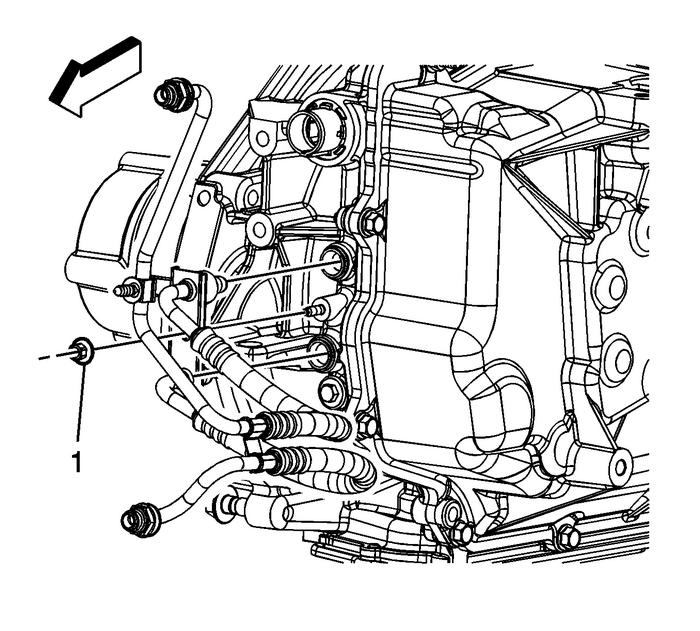
Drain the transaxle fluid.Remove the transaxle oil cooler line to transaxlenut-(1).Remove the transaxle oil cooler lines from thetransaxle.Remove the catalytic converter. Refer toCatalytic Converter Replacement.
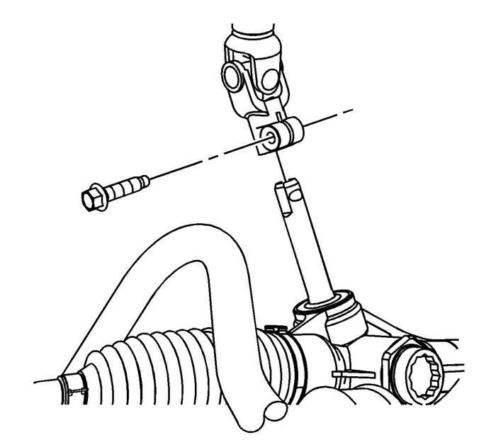
Note:Secure the steering wheel in the straight forward positionbefore separating the intermediate shaft from the steering gear, ordamage to the SIR coil will occur.
Remove the intermediate to steering gear pinch bolt anddisconnect the intermediate shaft from the steering gear. Discardthe pinch bolt.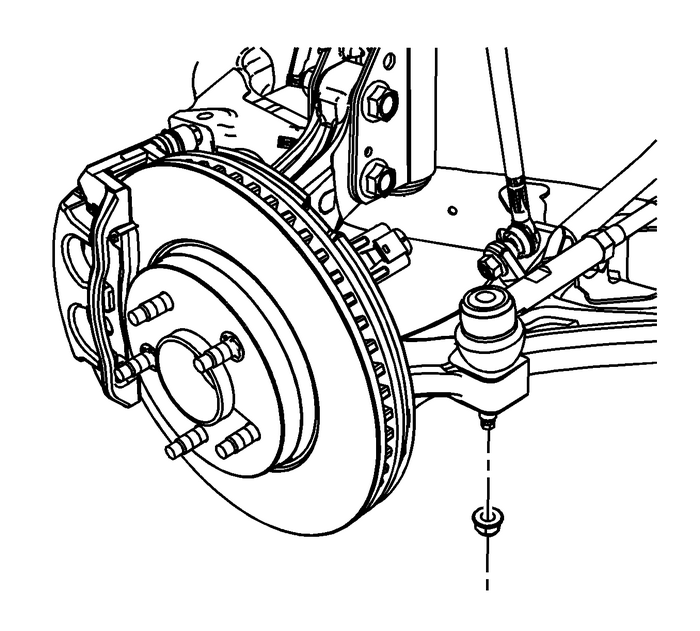
Remove and discard both outer tie rod to steering knucklenuts.
Note:Hold the ball stud to prevent turning during removal of thenut.
Use theCH-24319-Bpuller.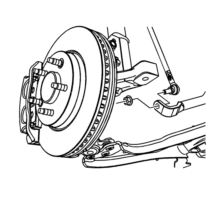
Remove the stabilizer link to stabilizer shaft nuts anddisconnect the stabilizer links from the stabilizer shaft.
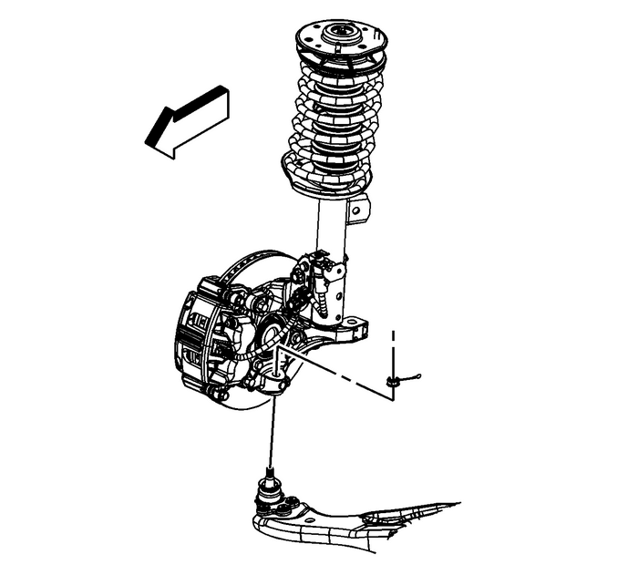
Remove and discard both of the lower control arm ball studcotter pins.Loosen the ball stud nuts until the nuts are level with thetop of the ball stud.
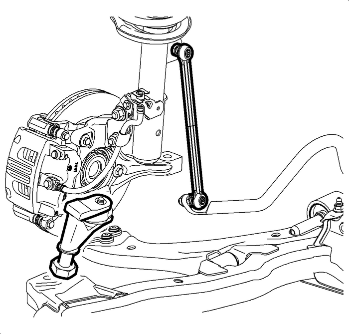
Use theJ-43828separator.Remove the ball stud nuts.Remove the wheel drive shafts. Refer toFront Wheel Drive Shaft Replacement.Lower the vehicle.
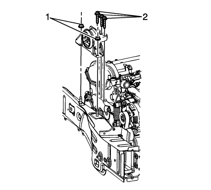
Remove the engine mount to engine mount bracketbolts-(2).
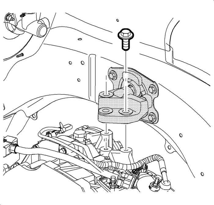
Remove the transaxle mount to transaxle adapter bolts.Disconnect electrical connectors and harnesses asnecessary.Raise the vehicle.
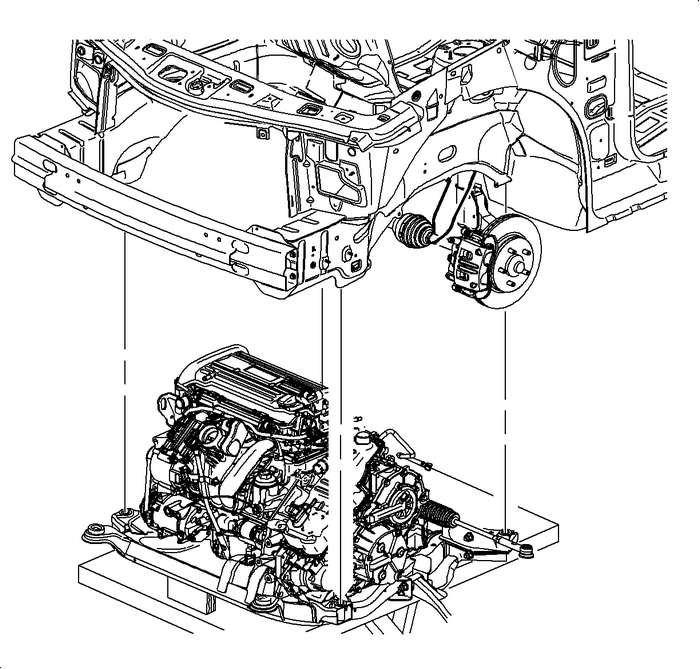
Note:During the powertrain removal support the vehicle body byplacing a jack at the rear of the vehicle.
Position a engine support table under the powertrainassembly.Note:Blocks of wood can be used between the front of the frame andthe oil pan to table in order to level the powertrain during theremoval.
With the table positioned, fully raise the table to contactwith the powertrain assembly.Remove the frame to body bolts. Discard the bolts.Note:When lowering the engine/transaxle assembly, verify all brakelines, shifter cables and other components are free duringremoval.
Lower the engine table and raise the body on the hoist untilthe engine/transaxle and cradle are free from the vehicle.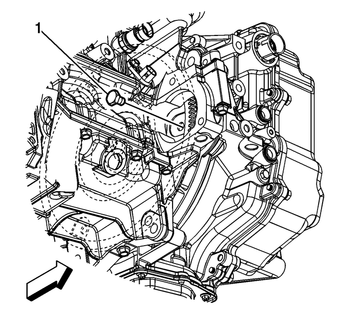
Remove the torque converter to flexplatebolts-(1).Disconnect the electrical harnesses as necessary.Install a suitable lifting devise to the engine.
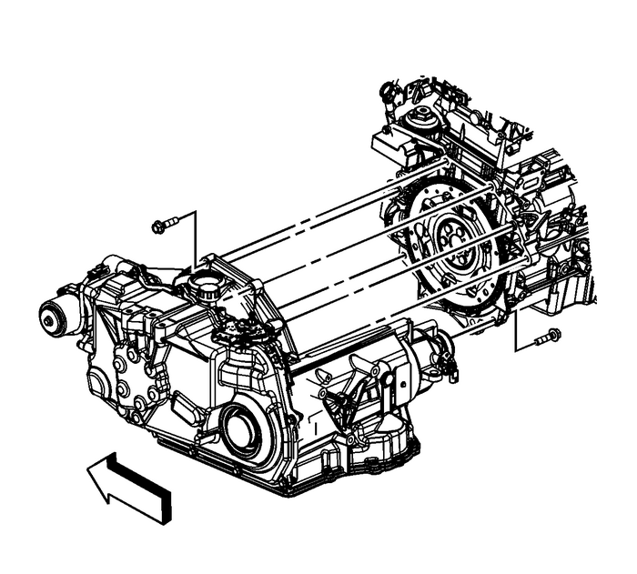
Remove the transaxle bolts from the engine.Separate the engine from the transaxle.Install the engine to a suitable engine stand.Installation Procedure

Install a suitable lifting devise to the engine.Using the lifting devise, position and install the engine tothe transaxle.
Caution:Refer toFastener Caution.
Install the transaxle bolts to the engine and tighten thebolts to75-Y(55-lb-ft).
Install the torque converter to flexplatebolts-(1) and tighten to62-Y(46-lb-ft).Connect the electrical harnesses as necessary.Remove the engine lifting devise.

Position the powertrain and support table under thevehicle.Raise the powertrain into position under the vehicle.With the table positioned, if required, lower the vehicleover the powertrain.Align the lower radiator pins with the frame. Ensure allhoses and electrical harnesses are correctly routed and free fromthe loading path of the powertrain.Install the NEW frame to body bolts and tighten to155-Y(114-lb-ft).Lower the vehicle.

Install the transaxle mount to transaxle adapter bolts andtighten to50-Y(37-lb-ft).

Install the engine mount to engine mount bracketbolts-(2).Tighten the engine mount to bracket bolts in the followingsequence:MiddleRearFront
Tighten the bolts to58-Y(43-lb-ft).
Raise and support the vehicle.Install the wheel drive shafts. Refer toFront Wheel Drive Shaft Replacement.
Install the control arm ball studs into the steeringknuckles.Install the ball stud nuts and tighten to10-Y(89-lb-in) plus165-degrees.Continue to tighten the nuts only enough to align the castlenut slots with the ball stud, install NEW cotter pins.

Connect the stabilizer links to the stabilizer shaft andinstall the stabilizer link to stabilizer shaft nuts. Tighten thenuts to85-Y(63-lb-ft).
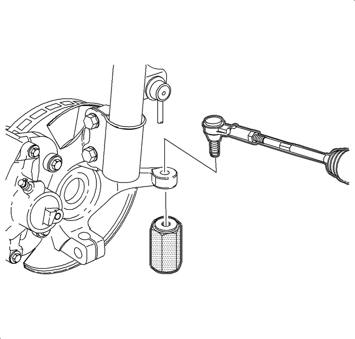
Connect the outer tie rods to the steering knuckles.Use theJ-44015installer.Remove theJ-44015installer.

Install NEW outer tie rod to steering knuckle nuts andtighten to25-Y(18-lb-ft) plus90-degrees.

Position the intermediate shaft to the steering gear andinstall a NEW pinch bolt.
Tighten the bolt to36-Y(27-lb-ft).
Install the catalytic converter. Refer toCatalytic Converter Replacement.
Install the transaxle oil cooler lines to thetransaxle.Install the transaxle oil cooler line to transaxlenut-(1) and tighten to22-Y(16-lb-ft).
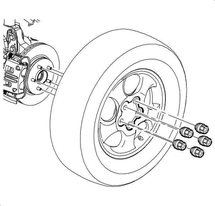
Remove the wood from between the oil pan and the enginecradle.Remove the wood from between the transaxle and the enginecradle.Install the engine splash shield. Refer toEngine Splash Shield Replacement - Left Side.Install the front wheels and tires. Refer toTire and Wheel Removal and Installation.Lower the vehicle.

Unsecure and position the radiator/condenser/fanassembly.

Install the shift control cable to the shift control cablebracket and engage the shift control cable retaining clip.Install the transaxle shift cable to the range selectlever.Raise and support the vehicle.Install the oxygen sensors. Refer toHeated Oxygen Sensor Replacement - Sensor 1andHeated Oxygen Sensor Replacement - Sensor 2.Instal the exhaust manifold heat shield. Refer toExhaust Manifold Heat Shield Replacement.Install the engine control module. Refer toEngine Control Module Replacement.Install the starter. Refer toStarter Replacement.
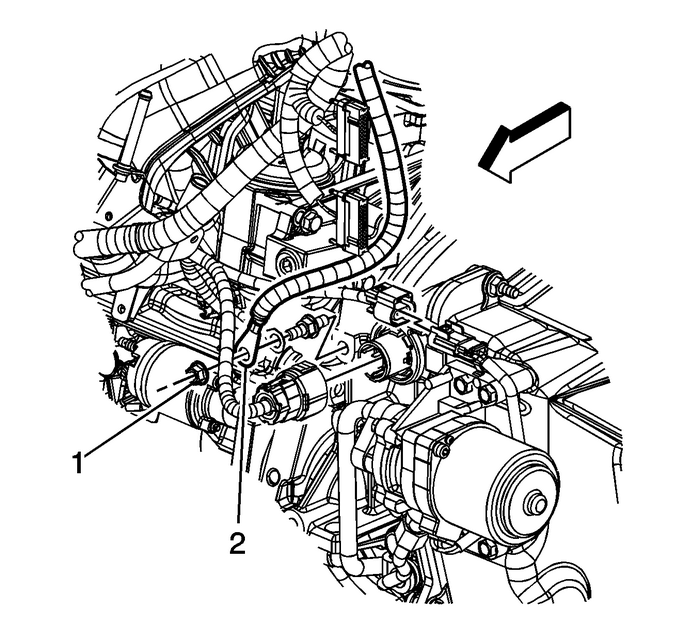
Position the negative battery cable and install the negativebattery cable lead-(2) to the transaxle stud.Install the engine wiring harness ground leadnut-(1) to the transaxle stud and tighten the nut to50-Y(37-lb-ft).

Position the A/C compressor and install the bolts and tightento22-Y(16-lb-ft).Connect the engine wiring harness electrical connector to theA/C compressor.Lower the vehicle.

Install the coolant recovery reservoir/heater inlethose-(2) to the thermostat housing.Position the coolant recovery reservoir/heater inlethose-(2) clamp at the thermostat housing.Install the heater inlet hose-(3) to thethermostat housing.Position the heater inlet hose clamp at the thermostathousing.

Connect the radiator inlet hose to the cylinder head.Reposition the radiator inlet hose clamp using theBO-38185pliers.Connect the radiator outlet hose. Refer toRadiator Outlet Hose Replacement.

Position and install the coolant recovery inlethose-(1) to the cylinder head.Install the coolant recovery inlet pipe to the fuel pumpcover.Install the coolant recovery inlet hose clamp-(2)at the cylinder head.

Position and install the vacuum brake boosterhose-(2) to the intake manifold.Position the vacuum brake booster hose clamp-(1)at the intake manifold.

Install the intake manifold. Refer toIntake Manifold Replacement.Install the fuel feed pipe clip-(2) to the fuelline bracket.Connect the EVAP line-(3) quick connect fitting tothe EVAP purge solenoid. Refer toPlastic Collar Quick Connect Fitting Service.Connect the fuel feed pipe-(1) quick connectfitting at the fuel rail. Refer toMetal Collar Quick Connect Fitting Service.Install the air cleaner outlet duct. Refer toAir Cleaner Outlet Duct Replacement.Install the air cleaner assembly. Refer toAir Cleaner Assembly Replacement.Fill the cooling system. Refer toCooling System Draining and Filling.Fill the transaxle with fluid. Refer toTransmission Fluid Drain and Fill.Refill the engine with oil. Refer toEngine Oil and Oil Filter Replacement.Perform the CKP system variation learn procedure. Refer toCrankshaft Position System Variation Learn.Start the engine and allow the engine to run, inspect forleaks. Correct as necessary.
 Tools and Equipment
Special tools are listed and illustrated throughout thissection with a complete listing at the end of the section. Thesetools, or their equivalents, are specially designed to quickly andsafely accompl ...
 Camshaft Cover Assemble Valvetrain Camshaft
Special ToolsDT 5590Bearing and Seal DriverJ-25254-AOil Seal InstallerFor equivalent regional tools, refer toSpecial Tools.Left Camshaft CoverInstall the NEW left spark plug shield tube seals using th ...
Other materials:
Drive Range, Third Gear Default Automatic Transmission Unit
If the transmission is in 1st, 2nd or 3rd gear during a transmission electrical componentfailure, the transmission will default to 3rd-gear. All solenoids will default totheir normal state. If the torque converter clutch was applied, it will release. Thisdefault action will enable the vehicle to be ...
