Chevrolet Equinox Service Manual: Crankshaft Balancer Installation Engine Block Cylinder Block Crankshaft
Special ToolsEN-48585 Crankshaft Balancer GuideEN-48953 Camshaft Actuator Locking ToolEN 38122-A Crankshaft Balancer HolderEN 43653 Flywheel Holding ToolEN 45059 Angle Meter
For equivalent regional tools, refer toSpecial Tools.

Caution:Ensure both components are aligned correctly or seriousengine damage will occur.
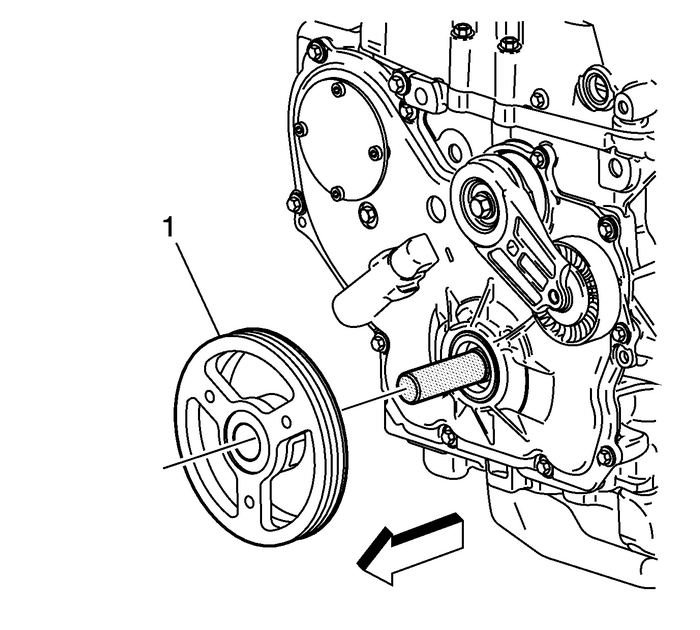
Install the EN 38122-A holder into the end of the crankshaft.Install the balancer-(1) onto the EN-48585 guide. Use care to properly align the keyway and flats on the balancer with the oil pumpdrive.
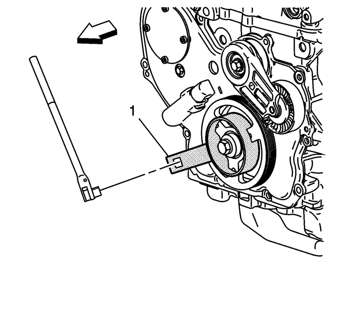
Note:EN 43653 locking tool may be used instead of EN 38122-A holder to prevent crankshaft rotation.
Install the EN 38122-A holder-(1).Caution:Refer toFastener Caution.
Note:Always install a new crankshaft balancer retaining bolt and washer.
Install a new retaining bolt and washer. Use the EN 38122-A holder and a breaker bar to prevent the crankshaft from rotating when tightening the bolt.Tighten the bolt to 150-Y (111-lb-ft) plus 100-degrees using the EN 45059 meter.
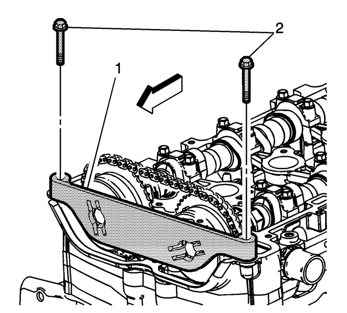
Install the EN-48953 locking tool-(1) and tighten the bolts into the cylinder head. Tighten the EN-48953 locking tool retaining bolts to 10-Y (89-lb-in).Release the timing chain tensioner by applying 45-Y (33-lb-ft) counterclockwise torque to the crankshaft balancer bolt.Remove the EN-48953 locking tool.
 Secondary Camshaft Intermediate Drive Chain Installation - Left Side Valvetrain Camshaft
Special ToolsEN 48383Camshaft Retaining ToolsEN 48589Crankshaft Rotation SocketFor equivalent regional tools, refer toSpecial Tools.Note:There should be no need to rotate the camshaft more than10-degr ...
 Crankshaft Sprocket Installation Engine Block Cylinder Block Crankshaft Sprocket
Special ToolsEN-48589Crankshaft Rotation SocketFor equivalent regional tools, refer toSpecial Tools.Ensure the crankshaft sprocket is installed with the timingmark-(1) visible.Install the crankshaft s ...
Other materials:
Transmission Identification Information Automatic Transmission Unit
617pakw7032ao00o45672425728600535631121ooooooooooxw1123653ulkx1234(1)Code for AutomaticTransmission(2)Model Year(3)Model for Transmission(4)Transmission Family(5)Source Code for Plant(6)Calendar Year(7)Julian Date(8)Shift/Line-(A/B)(9)Numeric sequence starting at0001-@-12:01-AM each day(10)Model Cod ...
