Chevrolet Equinox Service Manual: Crankshaft and Bearing Removal Engine Block Cylinder Block Crankshaft

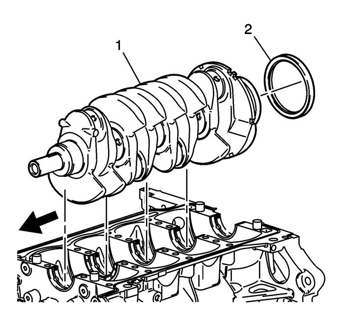
Remove the crankshaft-(1) from the block.Remove the crankshaft rear oil seal-(2) from theblock.

Note:Crankshaft bearings MUST be separated, marked, or organizedin a way to ensure installation to their original location andposition, when suitable for use.
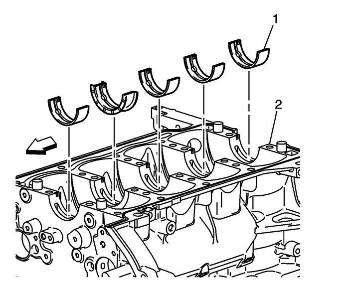
Remove the bearing inserts-(1) from theblock-(2).
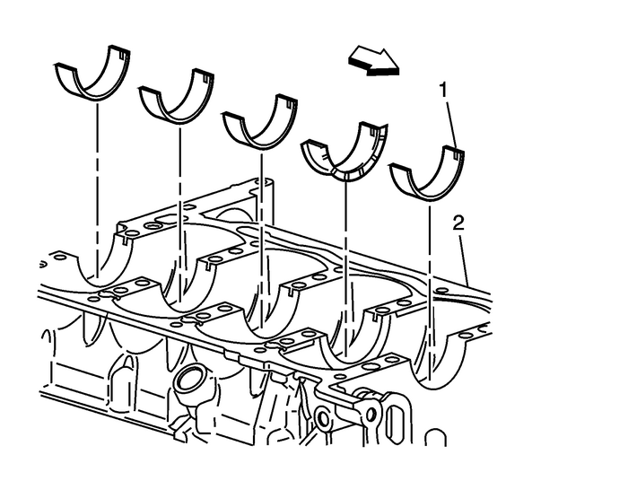
Remove the bearing inserts-(1) from the bedplate-(2).Clean the oil, sludge, and carbon.Inspect the oil passages for obstructions.Inspect the threads.Inspect the bearing journals and the thrust surfaces for thefollowing conditions:CracksChipsGougesRoughnessGroovesOverheating (discoloration)Inspect the corresponding bearing inserts for imbeddedforeign material. If foreign material exists find the cause andrepair it.
Note:Replace the crankshaft if cracks, severe gouges or burnedspots are found. Slight roughness may be removed with a finepolishing cloth soaked in clean engine oil. Burrs may be removedwith a fine oil stone.
Measure the crankshaft journals. Use a micrometer or dialindicator to measure the taper and runout. Note the result for thelater selection of bearing inserts. If not within limits thecrankshaft must be replaced.Note the location of the main bearing high spots. If they arenot in line, the crankshaft is bent and must be replaced.
 Engine Front Cover Removal Engine Block Cylinder Block Cyl Block Front Cover
Remove the camshaft position sensorbolts-(1).Remove the camshaft position sensors-(2).Remove the camshaft position actuator valvebolts-(1).Caution:The camshaft position actuator valves must be removed ...
 Crankshaft Rear Oil Seal and Housing Removal Engine Block Seals and Gaskets
Remove the crankshaft rear oil seal housing bolts.Use the pry points located at the edge of the crankshaft rearoil seal housing to separate the RTV sealant.Remove and discard the crankshaft rear oil s ...
Other materials:
Rear Bumper Impact Bar Replacement Bumpers Rear Bumper
Rear Bumper Impact Bar ReplacementCalloutComponent NamePreliminary ProcedureRemove the rear bumper fascia. Refer toRear Bumper Fascia Replacement.1Rear Impact Bar Bolt (Qty:-6)Caution:Refer toFastener Caution.Tighten25-Y(18-lb-ft)2Rear Impact Bar ...
