
Chevrolet Equinox Service Manual: Control Valve Channel Plate - Upper Body Spacer Plate Side Automatic Transmission Unit
Chevrolet Equinox Service Manual / Powertrain / Transmission/Transaxle / Control Valve Channel Plate - Upper Body Spacer Plate Side Automatic Transmission Unit
Control Valve Channel Plate– Upper Body Spacer Plate Side
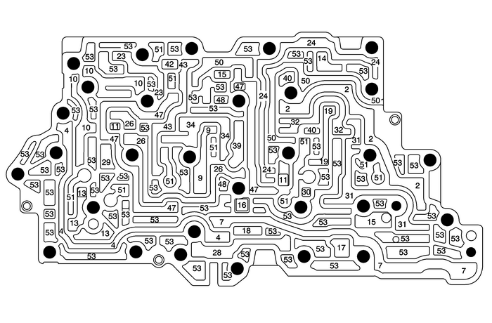
| (2) | Line |
| (4) | Converter Feed |
| (7) | Cooler Feed |
| (9) | Regulated Apply |
| (10) | Compensator Feed |
| (11) | Actuator Feed Limit |
| (13) | PCS Line |
| (14) | PCS R1/456 Clutch |
| (15) | Solenoid 1 |
| (16) | Solenoid 2 |
| (17) | CSV2 Enable |
| (18) | CSV3 Enable |
| (19) | R1/456 Clutch Feed |
| (23) | PCS 35 Reverse Clutch |
| (24) | Reverse |
| (26) | 35 Reverse Supply |
| (28) | 35 Reverse Clutch |
| (29) | 35 Reverse Clutch Feedback |
| (30) | PCS 1234 Clutch |
| (31) | Drive |
| (32) | Drive Brake |
| (34) | 26 Clutch/1234 Clutch Feed |
| (39) | Drive 1–6 |
| (40) | Latch Feed |
| (42) | PCS 26 Clutch |
| (43) | 26 Clutch |
| (47) | 456 Clutch |
| (48) | PCS TCC |
| (50) | Exhaust Backfill |
| (51) | Exhaust |
| (53) | Void |
 Control Valve Channel Plate Cleaning and Inspection Automatic Transmission Unit
Control Valve Channel Plate Cleaning and InspectionCalloutComponent NameCaution:After cleaning the transmission components, allow to air dry.Do not use cloth or paper towels in order to dry any transm ...
 Control Valve Channel Plate - Upper Plate Side Automatic Transmission Unit
Control Valve Channel Plate– Upper Plate Side(11)Actuator Feed Limit(13)PCS Line(14)PCS R1/456 Clutch(15)Solenoid 1(16)Solenoid 2(23)PCS 35 Reverse Clutch(30)PCS 1234 Clutch(35)Exhaust(40)Latch Feed ...
Other materials:
Oil Pump Disassemble Engine Lubrication Oil Pump
Remove the pressure relief plug-(1),spring-(2), and plunger-(3).Remove the oil pump gerotor cover-(1) andbolts.Clean all of the parts in cleaning solvent. Remove varnish,sludge and dirt.Inspect the oil pump-(2, 3) for wear and scoring.Ensure that all components are within specifications. Refer toEng ...
© 2017-2026 Copyright www.cequinox.com
