Chevrolet Equinox Service Manual: Case Cover Assembly Installation Automatic Transmission Unit

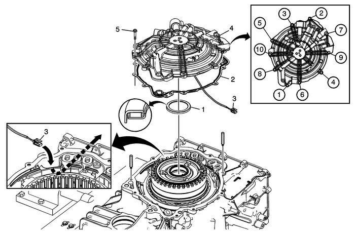
1 | Input Shaft Thrust Bearing Note:Note location of the orientation lip on bearing. All thrust bearings can only be assembledone way. |
2 | A/Trans Case Cover Gasket |
3 | Input Speed Sensor Wire Harness Note:Route the input speed sensor wire harness through the case passage. |
4 | A/Trans Case Cover Assembly ProcedureUse guide pins to install the case cover assembly to prevent damage to the input shaftthrust bearing.Pull the input speed sensor wire harness through the case passage while lowering thecover assembly onto the case.Special Tools 39068 Guide Pins For equivalent regional tools, refer toSpecial Tools. |
5 | A/Trans Case Cover Assembly Bolt-M6-x-30-(Qty:-10) Caution:Refer toFastener Caution. Procedure Tighten in sequence shown. Tighten12-Y (106-lb-in) |
 Case Cover and 3-5-Reverse and 4-5-6 Clutch Housing Removal Automatic Transmission Unit
Case Cover and 3-5-Reverse and 4-5-6 Clutch Housing RemovalCalloutComponent Name1A/Trans Case Cover Assembly Bolt-M6-x-30-(Qty:-10)2A/Trans Case Cover AssemblyCaution:Use care when pulling the input s ...
 Channel Plate - Control Solenoid (w/Body and TCM) Valve Assembly Side Automatic Transmission Unit
Channel Plate-–-ControlSolenoid (w/Body and TCM) Valve Assembly Side(2)Line(11)Actuator Feed Limit(12)PCS Line(13)PCS R1/456 Clutch(14)Shift Solenoid(18)PCS 35 Reverse Clutch(25)PCS 1234 Clutch(31)P ...
Other materials:
Fastener Tightening Specifications - Propeller Shaft Assembly Driveshafts Propeller Shaft Assembly
Fastener Tightening SpecificationsApplicationSpecificationMetricEnglishCenter Bearing-to-Vehicle Underbody Bolts25-Y19-lb-ftPropeller Shaft-to-Rear Differential Flange Bolts50-Y37-lb-ftPropeller Shaft-to-Transfer Case Flange Bolts35-Y25-lb-ft ...
