Chevrolet Equinox Service Manual: Wheel Drive Shaft Outer Joint Inspection Wheels
Disassembly ProcedureRemove the outer constant velocity (CV) joint and boot fromthe wheel drive shaft. Refer toFront Wheel Drive Shaft Outer Joint and Boot Replacement.Remove any lubricant from the CV joint.
Note:Position the cage and the inner race so they arelevel.
Install the outer CV joint assembly in a soft jawedvise.Note:The following procedure will have to be repeated until allthe ball bearing are removed form the cage.
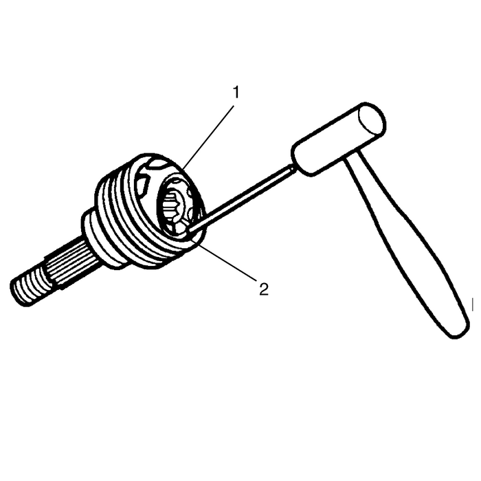
Using a brass drift-(1), gentle tap the cage untilthe ball bearing can be removed from the cage.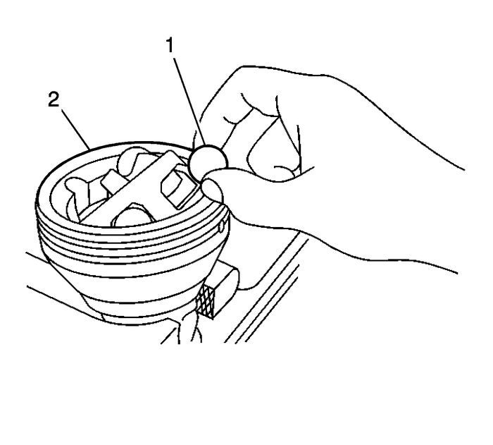
Using a small screwdriver, remove the ballbearings-(1) from the CV joint-(2).
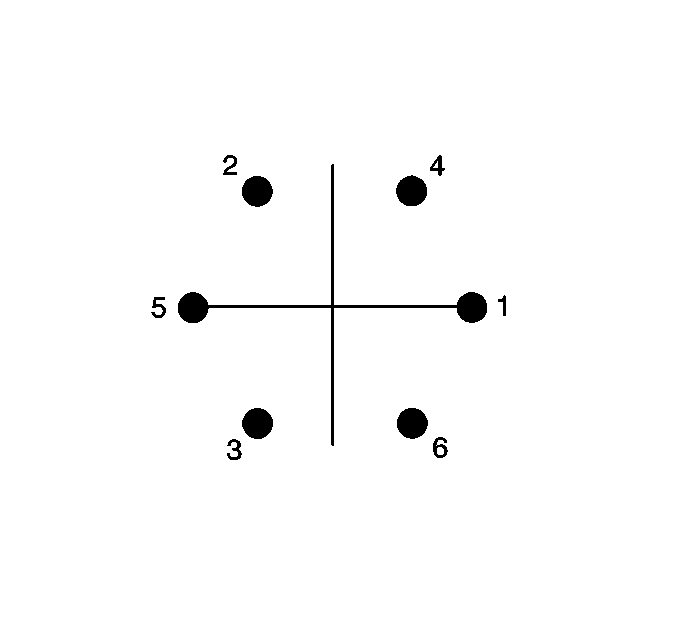
Remove the ball bearings from the CV joint insequence.
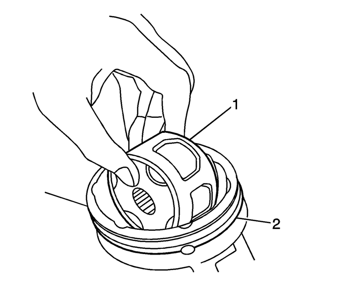
Note:Position the cage so that the larger radius corners of thecage windows are facing up.
Position the cage-(1) at a 90-degreesto the centerline of the outer race-(2).Align the cage windows with the lands of the outerrace-(2).Lift and remove the cage-(1) and the inner racefrom the outer race-(2).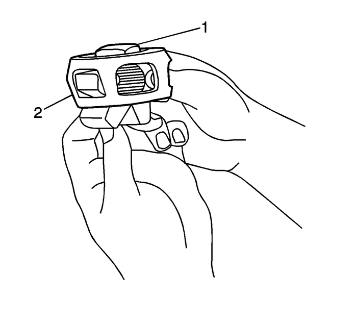
Position the cage-(2) and the innerrace-(1) so that the larger radius corners of the cagewindows are up.Rotate the inner race-(1) 90-degrees tothe center line of the cage-(2).Align the lands of the inner race-(1) with thewindows of the cage-(2).Move the inner race-(1) land into the cagewindow-(2).Rotate the inner race-(1) down and remove it fromthe cage-(2).Clean the following items thoroughly with the proper cleaningsolvent:The inner raceThe outer raceThe cageThe ball bearingsThe exposed end of the wheel drive shaft
Note:The internal parts of the CV joint are NOT SERVICEDseparately. The outer CV joint is serviced as an assembly.
If any of the above items are found to have excessive wear orare damaged, replace the outer CV joint as an assembly.Assembly Procedure
Position the cage-(2) so that the larger radiuscorners of the cage windows are up.Position the innerrace-(1)-90-degrees to thecenterline of the cage-(2).Insert the inner race-(1) through the bottom ofthe cage-(2).Align the lands of the inner race-(1) with thewindows of the cage-(2).Move the inner race-(1) land into the cagewindow-(2).Rotate the inner race-(1) down and remove it fromthe cage-(2).Rotate the inner race-(1) within thecage-(2) so that the grooved surface of the innerrace-(1) is facing up.Align the inner race-(1) ball bearing tracks withthe cage-(2) windows.

Wrap a clean shop towel around the CV joint outer racesplined shaft.Place the outer race-(2) vertically in a benchvise.Position the cage-(1) and the inner race at a90-degrees to the centerline of the outerrace-(2).With the inner race and the cage-(1) assembly in avertical position, insert the cage and the inner race into theouter race-(2).

Note:The larger radius corners of the cage windows should bepositioned up and the grooved surface of the inner race should bevisible.
Position the cage-(2) and the inner race so thatthey are level in the vise.Rotate the appropriate component(s), and align the cagewindows and the inner race ball bearing-(1) tracks withthe outer race ball bearing tracks.Position a cage window and the inner race ball bearing trackfor the ball bearing installation.Note:When performing the following procedure, the opposingcage-(2) window and the inner ballbearing-(1) track will be accessible for the ballbearing installation.
Press down on the cage following one of the outer race ballbearing-(1) tracks.Install the ball bearing through the cage window onto theinner race ball bearing-(1) track.Note:The following service procedure will have to be performedafter each ball bearing-(1) has been installed.
After the first ball bearing-(1) has beeninstalled, use a brass drift and a hammer and gently tap the cagein order to drive the cage and the inner race down completely inthe outer race.Note:After the ball bearing-(1) has been installed,there should be NO GAP between the ball bearing and the innerrace.
Position the cage and the inner race so that they arelevel.Using a plastic hammer, lightly tap the ballbearing-(1) into place.
Install the ball bearings in sequence.Repeatsteps-18-thru-20-untilall the ball bearings are installed.Install the outer CV joint and boot on the wheel drive shaft.Refer toFront Wheel Drive Shaft Outer Joint and Boot Replacement.
 Tire Dismounting and Mounting Wheels
Caution:Use a tire changing machine in order to dismount tires. Donot use hand tools or tire irons alone in order to remove the tirefrom the wheel. Damage to the tire beads or the wheel rim couldresul ...
 Fastener Tightening Specifications - Wheels Wheels
Fastener Tightening SpecificationsApplicationSpecificationMetricEnglishClamp Fit TPM Stem Locknut7-Y- Dynamically62-lb-inClamp Fit TPM Stem Locknut4-Y-Statically35-lb-in ...
Other materials:
Transmission Control Lever Knob Replacement Automatic Transmission Unit
Transmission Control Lever Knob ReplacementCalloutComponent Name1Shift Control KnobTip:Pull knob up off shift lever. Considerable effort may berequired to remove knob from shift control lever.Place shift lever in the Neutral position.2Shift Control ConnectorProcedureVerify the operation of the tap u ...
