Chevrolet Equinox Service Manual: Arrows and Symbols
Chevrolet Equinox Service Manual / Vehicle - General / Arrows and Symbols
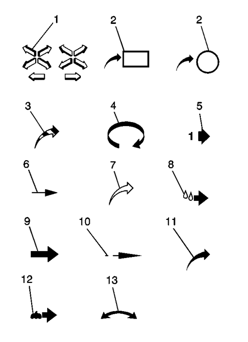
This service manual uses various symbols in order to describedifferent service operations.

| (1) | Front of Vehicle |
| (2) | View Detail |
| (2) | View Detail |
| (3) | Ambient Air Mixed with Another Gasor Indicate Temperature Change |
| (4) | Motion or Direction |
| (5) | View Angle |
| (6) | Dimension (1:2) |
| (7) | Ambient/Clean Air Flow or Cool AirFlow |
| (8) | Lubrication Point– Oil orFluid |
| (9) | Task Related |
| (10) | Sectioning (1:3) |
| (11) | Gas Other Than Ambient Air or HotAir Flow |
| (12) | Lubrication Point– Greaseor Jelly |
| (13) | Multidirectional Arrow |
 Vehicle Identification Number (VIN)
This legal identifier is in the front corner of the instrument panel, on the leftside of the vehicle. It can be seen through the windshield from outside. The VIN alsoappears on the Vehicle Certificati ...
 Interior Care
To prevent dirt particle abrasions, regularly clean the vehicle's interior. Immediatelyremove any soils. Note that newspapers or dark garments that can transfer color tohome furnishings can also perma ...
Other materials:
Manual Mode
Electronic Range Select (ERS) Mode
ERS or manual mode allows for the
selection of the range of gear
positions. Use this mode when
driving downhill or towing a trailer to
limit the top gear and vehicle speed.
The shift position indicator within the
Driver Information Center (DIC) will
displ ...
© 2017-2026 Copyright www.cequinox.com

