Chevrolet Equinox Service Manual: #10-00-89-005C: Warranty Administration - Revised Wiring Repair Labor Operations and Required Additional Information - (May 7, 2013)
| Subject: | Warranty Administration – Revised Wiring Repair Labor Operations and Required AdditionalInformation |
|
| Models: | 2014 and Prior GM Passenger Cars and Light Duty Trucks | |
This bulletin is being revised to add the 2014 model year and labor codes. Pleasediscard Corporate Bulletin Number 10-00-89-005B (Section 00 – General Information).
Beginning with 2010 model year vehicles, wiring repair labor operation numbers havebeen simplified to reduce the variation of choices. Additional data identifying thelocation of the repair is also now required in Global Warranty when submitting transactionsusing these labor operations. Additional required information may include:
SI Harness Routing View Document ID Number (wiring repairs)Grid Location from Routing View Document (wiring repairs)SI Connector End View Document ID Number (terminal/connector repairs)In SI for model year 2010 and newer vehicles, the Connector End View document IDsare unique for each illustration. For Harness Routing Views, a grid has been addedto provide the location area of repair. Follow the chart below to identify which informationis required for which labor operation.
Technicians - When you are perform a wiring system repair, follow SI diagnostics and refer to thetable below for the information that will be required from SI.
Wiring repairs will require the SI Document ID of the Harness Routing View, alongwith the grid coordinates (location) of the cause/repair.When connecting or repairing a connector, the required information will be the ConnectorEnd View Document DI. This applies to all connectors that plug into components (modules)or in-line connectors.Note:The additional data identifies the location of repair and will aid in failure analysisand future product quality enhancements.
Select the correct labor operation and write it and the additional required informationfor that operation on the repair order. In the Cause and Correction fields, be sureto indicate your observations on what the cause of the condition was (connector notconnected, terminal pushed out, loose ground fastener, etc.) and what you did to correctthe issue.
Warranty Claim Administrators - When one of the electrical labor operations listed in the chart below are used whensubmitting the warranty transaction, an additional required field will appear requestinga “Document ID.” Enter the required information shown in the chart below, which shouldbe documented on the repair order by the technician. The chart below identifies ifyou should be entering just a documentID, or a document ID AND a grid location.
Do not enter in this field bulletin numbers, PI numbers, schematic Doc IDs, connectornumbers (ie: x201), comments such as descriptive cause or corrections, or the word“None.”
Wrong Format | Correct Format |
Doc ID 1234567 | 1234567 |
Grid Location F12 | 1234567 F12 |
Note:This additional data identifies the location of the repair and must correspond withthe vehicle type and repair type entered.
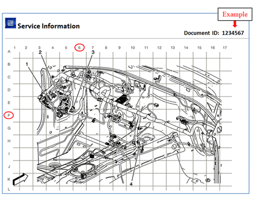
Examples of Information Required from SIRouting View Example
This technician used the SI document shown below to locate a chafed wire causing aninterior lamp issue. The technician repaired a circuit just left of the steering column.
When submitting the warranty transaction, the required information when using thislabor operation is the Document ID, immediately followed by the grid location whichidentifies the area of repair in the supplemental labor operation field. In this example,you would enter 1234567 F6.

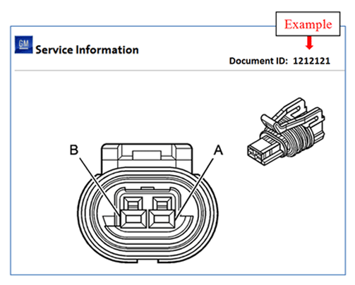
Connector view Example
The SI document shown below identifies a connector that was not fully seated causinga check engine light. The technician inspected the connector and found it only neededto be fully engaged to correct the condition. No parts were needed for this repair.
When submitting the warranty transaction, the required information when using thislabor operation is simply the Document ID identifying the connector. In this example,you would enter 1212121.

Labor Operation | Labor Operation Description | Supplemental Information Required | Notes for Use of This Labor Operation | |
5430840 | Terminal Replacement | Document ID of the Connector End View connected or repaired | Use for terminal replacement or terminated leads. This may be due to a spread terminalcondition, corrosion or will not stay retained in the connector body. | |
5430860 | Connector Kit Replacement | Document ID of the Connector End View of connector repaired | Use when replacing plastic connector body with nine or greater circuit cavities.Kits include connector body, CPA and TPA but do not come with terminals or terminatedleads. | |
5430880 | Connector with Leads Assembly Replacement | Document ID of the Connector End View of connector repaired | Plastic connector with eight or less circuits – includes terminated leads (pigtail). | |
5430902 | Wire-to-Wire Repair | Document ID of the Harness Routing View of repaired harness PLUS grid location showing repair area | Repair is to wiring only – not to be used if a terminal or connector was repairedor replaced. | |
5430922 | Connector Reconnection | Document ID of Connector End View of connector that was not connected properly | Electrical connections only – connectors not fully seated or totally disconnected.Also used when a loose fastener is causing a poor electrical connection (i.e. looseground bolt/nut). | |
5430940 | Harness Replacement | Document ID that best depicts that area of repair (Harness Routing View or ConnectorEnd View) | Used only when replacing a complete harness assembly. | |
5430962 | Ground Connection Repair | Document ID of Locator View of ground fastener which required repair. (Ground locationsare linked from the Master Electrical Component List in SI) | Use when tightening or reconnecting grounds. Use ground stud repair if the groundstud was broken. | |
GM bulletins are intended for use by professional technicians,NOT a "do-it-yourselfer". They are written to inform thesetechnicians of conditions that may occur on some vehicles, or toprovide information that could assist in the proper service of avehicle. Properly trained technicians have the equipment,tools, safety instructions, and know-how to do a job properly andsafely. If a condition is described, DO NOT assume that thebulletin applies to your vehicle, or that your vehicle will havethat condition. See your GM dealer for information on whetheryour vehicle may benefit from the information. |
| WE SUPPORT VOLUNTARY TECHNICIAN CERTIFICATION |
 #11-00-89-007C: Warranty Administration - Revised Exterior Labor Operations (Labor Only-No Part Replaced) and Required Warranty Claim Submission Information...
Subject:Warranty Administration - Revised Exterior Labor Operations (Labor Only - No PartReplaced) and Required Warranty Claim Submission InformationModels: 2014 and Prior GM Passenger Cars and Light ...
 Front View Camera Module Scan Tool Information
Table 1: Front View Camera Module Scan Tool Data ParametersTable 2: Front View Camera Module Scan Tool Output ControlsFront View Camera Module Scan Tool Data ParametersParameterSystem StateExpected Va ...
Other materials:
Camshaft Removal - Right Side Valvetrain Camshaft
Observe the markings on the bearing caps. Each bearing cap is marked in order to identifyits location. The markings have the following meanings:The raised feature must always be oriented toward the center of the cylinder head.The I indicates the intake camshaft.The E indicates the exhaust camshaft.T ...


