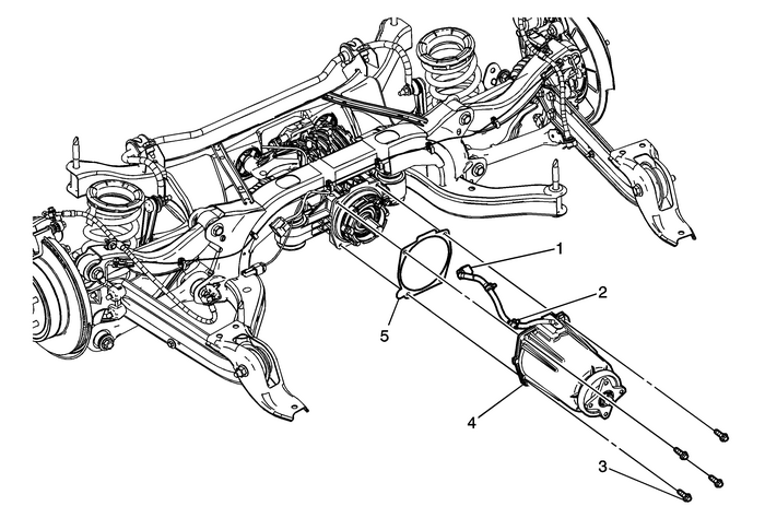
Chevrolet Equinox Service Manual: Rear Wheel Drive Module Clutch Housing Replacement Wheels

| Preliminary ProceduresRaise the vehicle. Refer toLifting and Jacking the Vehicle.Remove the propeller shaft from the differential clutch drumassembly. Refer toPropeller Shaft Replacement. | |
1 | Electrical Clutch Control Connector |
2 | Retaining Clip (Qty:-2) |
3 | Differential Clutch Drum Bolt (Qty:-4) Caution:Refer toFastener Caution. Tip:Relocate the rear portion of the propeller shaft to the sideand support it with mechanics wire or equivalent. Tighten29-Y(21-lb-ft) |
4 | Differential Clutch Drum Procedure Rear differential clutch control module recalibration, refertoControl Module References. Tip:The pinion flange, dust cover and pinion nut are servicedwith the differential clutch drum assembly. |
5 | Differential Clutch Drum Gasket Tip:Apply a small amount of grease to the gasket to hold it inplace. |
 Front Camber Adjustment Wheels
Raise and support the vehicle. Refer toLifting and Jacking the Vehicle.Remove the wheel and tire assemblies. Refer toTire and Wheel Removal and Installation.Remove the strut to knuckle nuts and bolts. ...
 Tire and Wheel Removal and Installation Wheels
Removal ProcedureRaise and support the vehicle. Refer toLifting and Jacking the Vehicle.If rotating the tires, refer toTire Rotation.Remove the wheel center cap, if equipped.Remove the wheel center ca ...
Other materials:
Control Valve Upper Body Assembly - Upper Body Spacer Plate Side Automatic Transmission Unit
Control Valve Upper Body Assembly– Upper Body Spacer Plate Side(2)Line(3)Decrease(4)Converter Feed(5)TCC Release(6)TCC Apply(7)Cooler Feed(9)Regulated Apply(10)Compensator Feed(11)Actuator Feed Limit(13)PCS Line(14)PCS R1/456 Clutch(15)Solenoid 1(17)CSV2 Enable(18)CSV3 Enable(19)R1/456 Clutch Feed ...
