
Chevrolet Equinox Service Manual: Internal Components Removal Automatic Transmission Unit
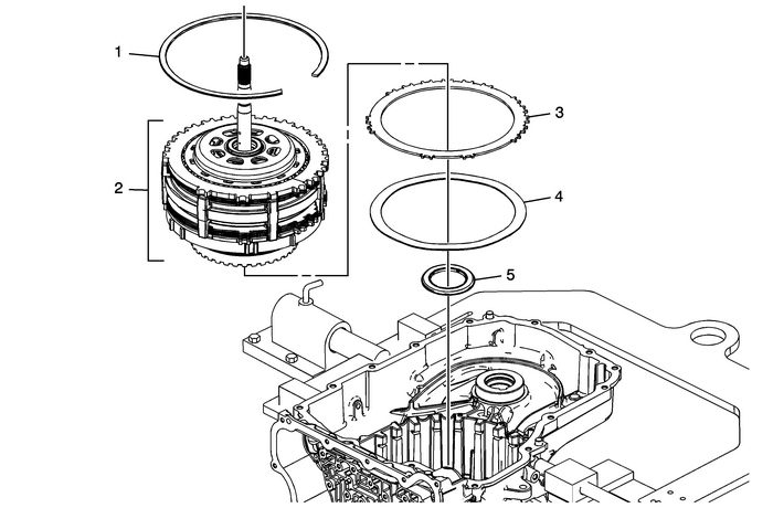
1 | 1–2–3–4 Clutch Backing Plate Retainer Ring Warning:The retainer is under tension. Use care when removing orinstalling the retainer. Personal injury could result. Caution:Use caution during removal or installation of the retainerring to avoid damage to the case machined surface in the park pawlarea. Burrs or raised edges on the case machined surface can causethe park pawl to bind and prohibit it from engaging the parkgear. Note:Remove one end of the retainer using DT-28585 snap ring remover or equivalent and work the retainer out of the case groove. Special Tool DT-28585 Snap Ring Remover or equivalent For equivalent regional tools, refer toSpecial Tools. |
2 | 3–5 Reverse and 4–5–6 Clutch Housing Assembly, Gearset, Low-Reverse Clutch Assemblyand Low-Reverse and 1–2–3–4 Clutch Housing Note:This unit is heavy-–-weighs-40-lbs.-(18-Kg). |
3 | 2–6 Clutch Plate-(Qty:-1) |
4 | 2–6 Clutch Apply Plate-(Waved) |
5 | 35R and 456 Clutch Housing Thrust Bearing Assembly |
 Air Conditioning Clutch Drive Plate Adjustment Flywheel/Flexplate
Install the clutch plate assembly.Note:Ensure the drive plate does not drag against the pulley whenthe pulley is rotated.Measure the air gap between the pulley and the drive plate.Adjust the shims to ...
 Lift Plate and Holding Fixture Installation Automatic Transmission Unit
Lift Plate and Holding Fixture InstallationCalloutComponent Name1DT-47811-ATransmission Lift PlateWarning:Handle with care, the transmission assembly weighs over83-Kg (183-lbs). Bodily injury could oc ...
Other materials:
Propeller Shaft Replacement Driveshafts Propeller Shaft Assembly
Removal ProcedurePlace the transmission in neutral-(N).Raise and support the vehicle. Refer toLifting and Jacking the Vehicle.Mark the relationship of the propeller shaft to the reardifferential drive flange and the transfer case.Support the propeller shaft at the rear differential.Remove the mounti ...
