Chevrolet Equinox Service Manual: Fuel Pressure Gauge Installation and Removal Engine Control
Special Tools
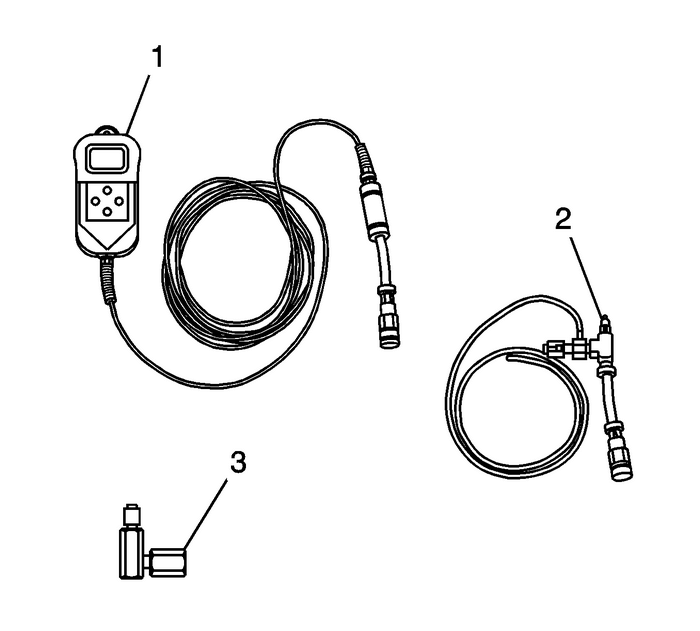
CH 48027 Digital Pressure Gauge
For equivalent regional tools, refer toSpecial Tools
Installation ProcedureWarning:Refer toGasoline/Gasoline Vapors Warning.
Warning:Remove the fuel tank cap and relieve the fuel system pressurebefore servicing the fuel system in order to reduce the risk ofpersonal injury. After you relieve the fuel system pressure, asmall amount of fuel may be released when servicing the fuel lines,the fuel injection pump, or the connections. In order to reduce therisk of personal injury, cover the fuel system components with ashop towel before disconnection. This will catch any fuel that mayleak out. Place the towel in an approved container when thedisconnection is complete.

Relieve the fuel system pressure. Refer toFuel Pressure Relief.Remove the intake manifold cover. Refer toIntake Manifold Cover Replacement.Connect the CH 48027 gauge(1) to the CH 48027 adapter(2).Remove the shop towel from around the fuel rail service port, and place in an approvedgasoline container.Perform any tests and/or diagnostics as needed. For the proper usage of the CH 48027 gauge(1), refer to the manufacture's directions.Removal Procedure

Warning:Wrap a shop towel around the fuel pressure connection inorder to reduce the risk of fire and personal injury. The towelwill absorb any fuel leakage that occurs during the connection ofthe fuel pressure gauge. Place the towel in an approved containerwhen the connection of the fuel pressure gauge is complete.
Relieve the fuel system pressure, if required. Perform the following steps:Wrap a shop towel around the fuel rail service port.Place the hose on the CH 48027 adapter(2) into an approved gasoline container.Open the valve on the CH 48027 adapter(2) in order to bleed any fuel from the fuel rail.Close the valve on the CH 48027 adapter(2).Remove the hose on the CH 48027 adapter(2) from the approved gasoline container.Remove the shop towel from around the fuel rail service port, and place in an approvedgasoline container.Caution:Clean all of the following areas before performing anydisconnections in order to avoid possible contamination in thesystem:
The fuel pipe connectionsThe hose connectionsThe areas surrounding the connectionsDisconnect the CH 48027 gauge(1) from the CH 48027 gauge(2).Disconnect the CH 48027 adapter(2) from the CH 48027 adapter(3).Disconnect the CH 48027 adapter(3) from the fuel rail service port.Install the fuel rail service port cap.Install the intake manifold cover. Refer toIntake Manifold Cover Replacement.Tighten the fuel fill cap. Fuel Tank Draining Engine Control
Special ToolsCH-45004Fuel Tank Drain HoseFor equivalent regional tools, refer toSpecial Tools.Warning:Never drain or store fuel in an open container. Always use anapproved fuel storage container in or ...
 Fuel Tank Fuel Pump Module Replacement - Secondary (With Out) Engine Control
Special Tools CH-48482 Fuel Tank Sender WrenchFor equivalent region tools, refer toSpecial Tools.Removal ProcedureWarning:Refer toGasoline/Gasoline Vapors Warning.Remove the fuel tank. Refer toFuel Ta ...
Other materials:
3-5-Reverse and 4-5-6 Clutch Housing Disassemble (6T40/45/50 - Gen 2) Automatic Transmission Unit
Table 1: Turbine Shaft, Reluctor Wheel and Piston RemovalTable 2: 4–5–6 Clutch Plate RemovalTable 3: 4–5–6 Clutch Piston RemovalTable 4: Reluctor Wheel and Piston RemovalTable 5: 3–5 Reverse Clutch Plate RemovalTurbine Shaft, Reluctor Wheel and Piston RemovalTurbine Shaft, Reluctor Wheel a ...
