Chevrolet Equinox Service Manual: Control Solenoid Valve and Transmission Control Module Assembly Inspection Automatic Transmission Unit

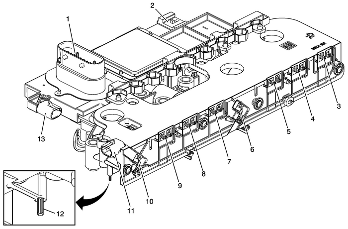
Inspect the control solenoid valve assembly connectors and pins-(1, 2, 11, 13) forthe following conditions:DamageBent pinsDebrisBroken retaining tabContaminationEnsure no metallic debris is inside the connectors near the terminal pins.Inspect the control solenoid valve assembly solenoid leads-(3) for contamination ormetallic debris.Inspect the 4 control solenoid valve assembly filter plate retaining tabs-(12) forcracks and ensure proper tension when filter plate is attached.
Line Pressure Control Solenoid | 3 | 4.5–5.2-Ω |
Pressure Control Solenoid-2-(PCS2) | 5 | 4.5–5.2-Ω |
Pressure Control Solenoid-3-(PCS3) | 9 | 4.5–5.2-Ω |
Pressure Control Solenoid-4-(PCS4) | 4 | 4.5–5.2-Ω |
Pressure Control Solenoid-5-(PCS5) | 8 | 4.5–5.2-Ω |
Shift Solenoid-1-(SS1) | 10 | 22–25-Ω |
Shift Solenoid-2-(SS2) | 6 | 22–25-Ω |
Torque Converter Clutch-(TCC) Pressure Control Solenoid | 7 | 4.5–5.2-Ω |
 Input Speed Sensor Seal Replacement Automatic Transmission Unit
Input Speed Sensor Seal ReplacementCalloutComponent NamePreliminary ProceduresRaise and support the vehicle. Refer toLifting and Jacking the Vehicle.Drain the transmission, refill when repair is compl ...
 Air Conditioning Clutch Drive Plate Adjustment Flywheel/Flexplate
Install the clutch plate assembly.Note:Ensure the drive plate does not drag against the pulley whenthe pulley is rotated.Measure the air gap between the pulley and the drive plate.Adjust the shims to ...
Other materials:
#99-08-51-001C: Paint-less Dent Repair Process - (Feb 25, 2013) Emblems/Decals/Paint
Subject:Paint-less Dent Repair ProcessModels: 2014 and Prior GM Passenger Cars and Light Duty Truckswith Steel Outer Body PanelsThis bulletin is being revised to add the 2013 and 2014 model years. Please discardCorporate Bulletin Number 99-08-51-001B (Section 08 – Body and Accessories).The proces ...
