Chevrolet Equinox Service Manual: Rear Drive Axle Description and Operation Axles Rear

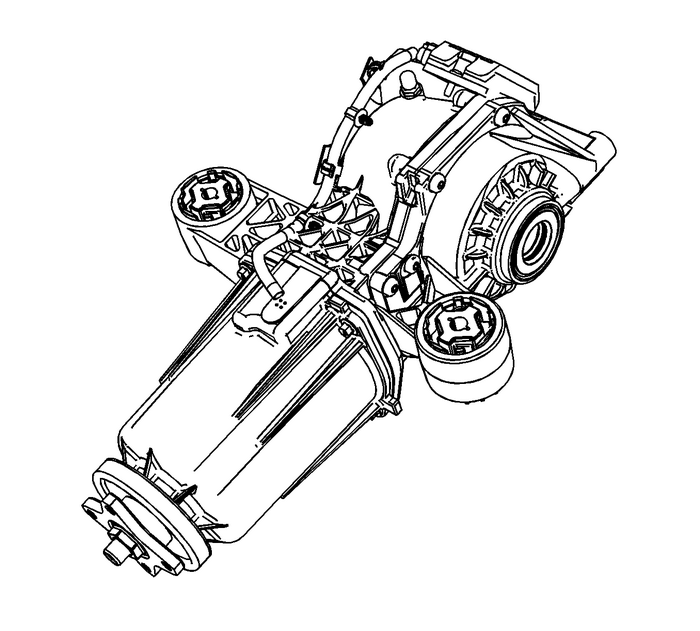
The rear differential assembly in this vehicle consists of an aluminum housing whichcontains a electric clutch/coupler and a differential. The differential fluid is onlycontained in the differential housing portion.
The clutch and clutch housing are serviced as an assembly. The fluid level range forproper rear differential assembly operation is 500-ml. New service replacement unitswill be shipped dry (without fluid). Fill new units with 500-ml of GL-Synthetic fluid.
Rear Drive Axle Electrical ConnectivityRear Drive Axle Block DiagramP16Instrument ClusterB5LFWheel Speed Sensor - Left FrontB5RFWheel Speed Sensor - Right FrontB5LRWheel Speed Sensor - Left RearB5RRWheel Speed Sensor - Right RearK17Electronic Brake Control ModuleK20Engine Control ModuleB99Steering Wheel Angle SensorK47Rear Differential Clutch Control ModuleP9Driver Information Center DisplayQ28Rear Drive ClutchHard-Wired
Serial Data
P16-Instrument Cluster
B5LF-Wheel Speed Sensor – Left Front
B5RF-Wheel Speed Sensor – Right Front
B5LR-Wheel Speed Sensor – Left Rear
B5RR-Wheel Speed Sensor – Right Rear
K17-Electronic Brake Control Module
K20-Engine Control Module
B99-Steering Wheel Angle Sensor
K47-Rear Differential Clutch Control Module
P9-Driver Information Center Display
Q28-Rear Drive Clutch
The rear drive axle system operates as follows:
System distributes torque evenly between the 2 rear wheels.The system distributes torque to the rear wheels to enhance traction and improve vehiclehandling performance.The rear differential clutch control assembly contains a main clutch, pilot clutch,electromagnetic coil, rear wheel shaft, main cam, pilot cam.The rear differential clutch control module operates by utilizing a clutch pack fortransferring torque. The engagement mechanism consists of an electromagnetic coiland armature which modulates torque through a pilot clutch and thrust amplificationdevice.The rear differential has a micro computer which receives information from the reardifferential clutch control module.The rear differential clutch control module has an internal temperature sensor, whichwill maintain consistent and continuous temperature compensation for torque transferfrom −40°C to +120°C. When the temperature of the module is determined to be beyondits limits, the rear differential clutch control module will temporarily disable therear drive system and turn on the AWD Disabled message. When the temperature of themodule isback within the limits, the rear differential clutch control module will enable therear drive system. The temperature sensor and coil are internal to the rear differential,and is replace as an assembly.If the vehicle is being driven very aggressively or an unexpected tire size has beenused, the AWD disabled message will be turned on. This should not result in the replacementof rear differential clutch control module.The AWD disable message will be turned on if the mini-spare tire or a very small sizedtire has been installed. This should not result in the replacement of rear differentialclutch control module.The rear wheel drive clutch coil receives current from the rear differential clutchcontrol module which is used to modulate torque through the use of the engagementmechanism. The greater the current, the greater the torque. The safe current rangeis between 0.1–3.0-A. If the current range is not within those values DTCs are setand the Service AWD message will appear. The temperature sensor and rear wheel driveclutch coilare internal to the differential and are replaced as an assembly.The module uses vehicle speed, steering angle, wheel slip, thermal compensation, andchassis control intervention to determine current. These are serial data messagesreceived from other modules.If replacing the rear differential clutch control module, the module needs to be configuredfor the clutch control calibrations. The connector for the rear wheel drive clutchthat connects to the rear differential clutch control module will have a 2 digit codeon it. Use that 2 digit code to program the rear differential clutch control moduleusing the scan tool.Voltage to the module is between 9–16-V. The module will set a low voltage DTC anda high voltage DTC to indicate voltage value out of range.The driver information center can display a Service All Wheel Drive message. The instrumentpanel cluster Amber AWD icon will illuminate when the system is disabled . Propeller Shaft Description and Operation Driveshafts Propeller Shaft Assembly
The propeller shaft assembly is a 2-piece design.The front shaft consists of a plunging A-type constantvelocity joint at the front and a universal joint and yoke at therear.The rear shaft consists of ...
 Differential Housing Support Bushing Replacement (Rear) Differentials Differential Carrier
Tools Required J-45725 Cradle Bushing ReplacerRemoval ProcedureRaise and support the vehicle. Refer toLifting and Jacking the Vehicle.Remove the rear differential assembly. Refer toDifferential Replac ...
Other materials:
Rear Side Door Replacement Panels
Rear Side Door ReplacementCalloutComponent NameWarning:Refer toSIR Warning.Preliminary ProceduresDisable the supplemental inflatable restraint (SIR) system.Refer toSIR Disabling and Enabling.Remove the rear door trim panel. Refer toRear Side Door Trim Panel Replacement.Remove rear side door check li ...
