Chevrolet Equinox Service Manual: Parking Brake Lever Replacement Parking Brake Lever or Pedal
Special Tools
J-37043Parking Brake Cable Release Tool
Removal ProcedureRaise and support the vehicle. Refer toLifting and Jacking the Vehicle.
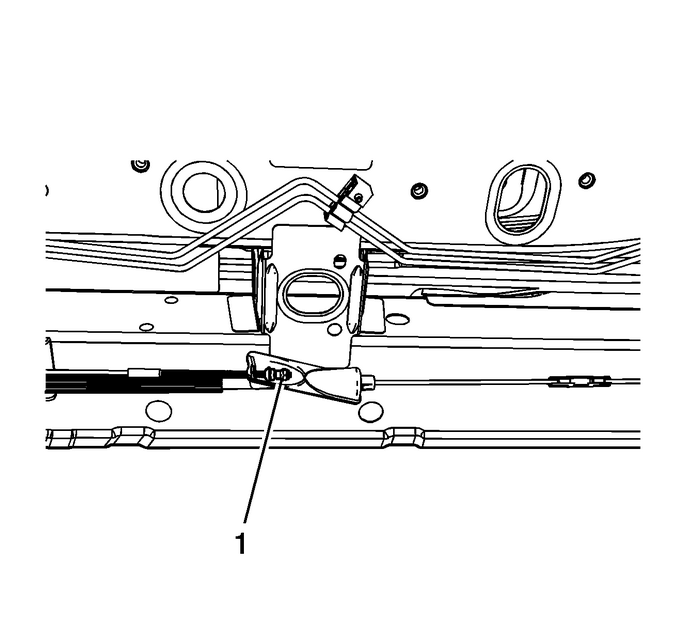
Loosen the park brake cablelocknut-(1)-at the equalizer to relievetension on the park brake cable.Lower the vehicle.Remove the left side body hinge pillar trim panel. Refer toBody Hinge Pillar Trim Panel Replacement.Remove the left side instrument panel insulator panel. RefertoInstrument Panel Insulator Panel Replacement - Left Side.Disconnect the park brake warning indicator switch electricalconnector.

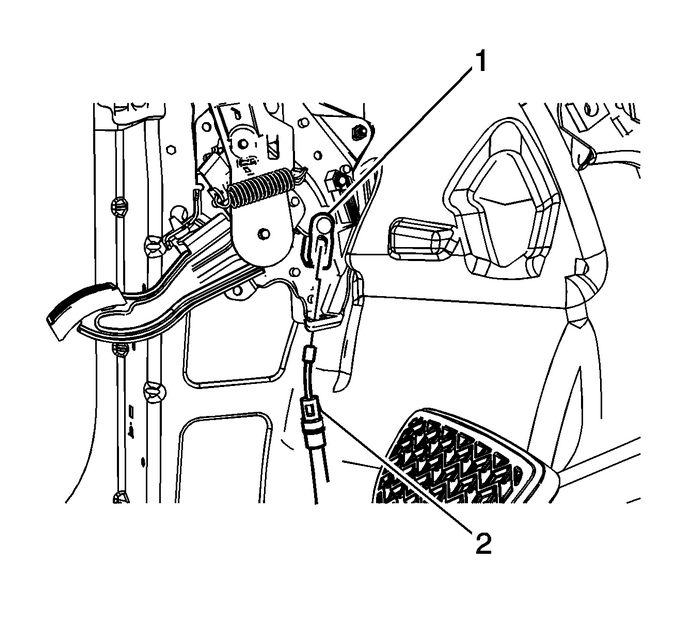
Disconnect the front park brake cable from the park brakepedal clevis-(1).Using theJ-37043Parking Brake Cable Release Tool, remove the front park brake cable from the park brakepedal assembly by compressing the locking tabs on the cableconduit-(2).

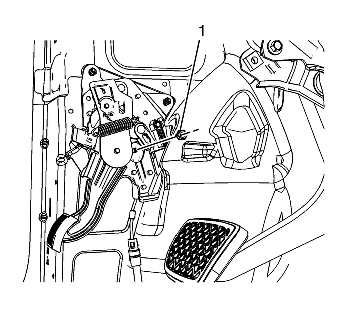
Remove the lower park brake pedal nut-(1).

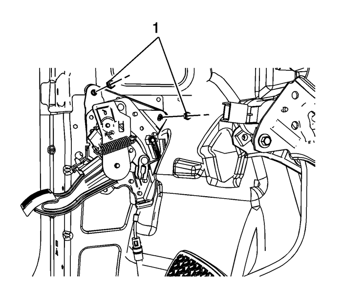
Remove the-2-upper park brake pedalnuts-(1).Remove the park brake pedal assembly.Installation Procedure

Install the park brake pedal assembly.
Caution:Refer toFastener Caution.
Install the-2-upper park brake pedalnuts-(1)-and tighten to-10-Y(89-lb-in).
Install the lower park brake pedalnut-(1)-and tighten to-10-Y(89-lb-in).

Connect the front park brake cable to the park brake pedalclevis-(1).Install the front park brake cable to the park brake pedalassembly.Ensure the locking tabs on the cableconduit-(2)-are fully engaged to the parkbrake pedal assembly.Connect the park brake warning indicator switch electricalconnector.Install the left side instrument panel insulator panel. RefertoInstrument Panel Insulator Panel Replacement - Left Side.Install the left side body hinge pillar trim panel. Refer toBody Hinge Pillar Trim Panel Replacement.Adjust the park brake. Refer toParking Brake Adjustment.
 Brake Pedal Travel Measurement and Inspection Hydraulic Brakes Brake Pedal Assembly
Special ToolsJ-28662Brake Pedal Effort Gauge, or equivalentWith the ignition OFF and the brakes cool, apply the brakes3–5-times, or until the brake pedal becomesfirm, in order to deplete the brake b ...
 Parking Brake Rear Cable Replacement (Right) Parking Brake
Special ToolsJ-37043Parking Brake Cable Release ToolRemoval ProcedureRelease the park brake.Raise and support the vehicle. Refer toLifting and Jacking the Vehicle.Loosen, but do not remove the park br ...
Other materials:
Operation Entertainment Audio-Visual
ControlsThe infotainment system is operated by using the pushbuttons, multifunction knobs,display menus, and steering wheel controls, if equipped.Turning the System On or OffVOL/ O (Volume/Power)Press to turn the system on and off.Automatic Switch-OffIf the infotainment system has been turned on aft ...
