Chevrolet Equinox Service Manual: Intake Manifold Installation Intake and Forced Induction Intake Manifold
Special Tools
EN-48896 HP Fuel Pump Installation Alignment Gauge
For equivalent regional tools, refer toSpecial Tools.
Caution:Refer toFastener Caution.
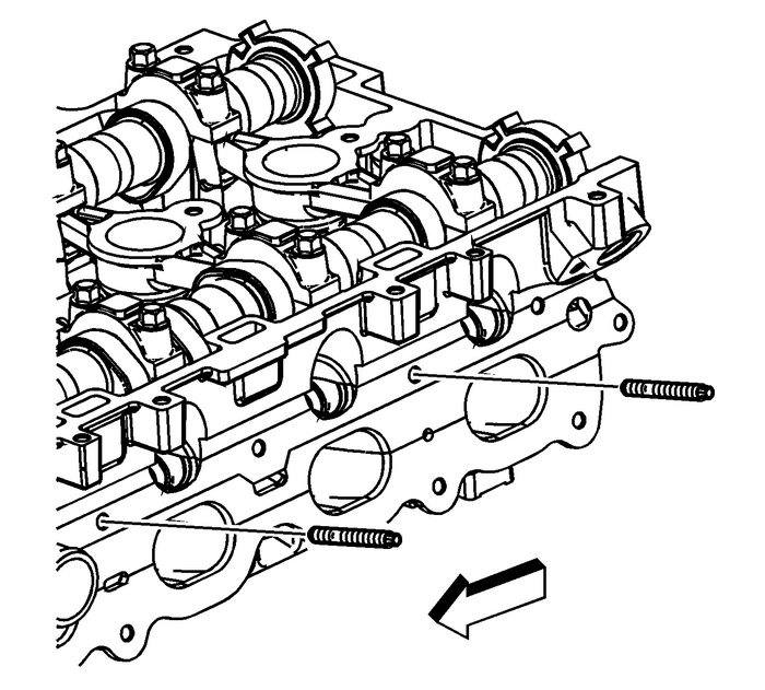
Install the intake manifold studs in the manifold face and tighten to 15-Y (11-lb-ft).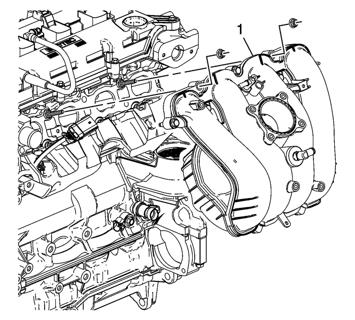
Install the intake manifold-(1). Start and hand tighten the intake manifold boltsand nuts.
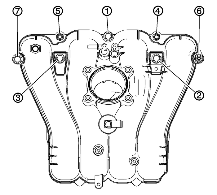
Tighten the bolts and nuts in sequence to 25-Y (18-lb-ft).
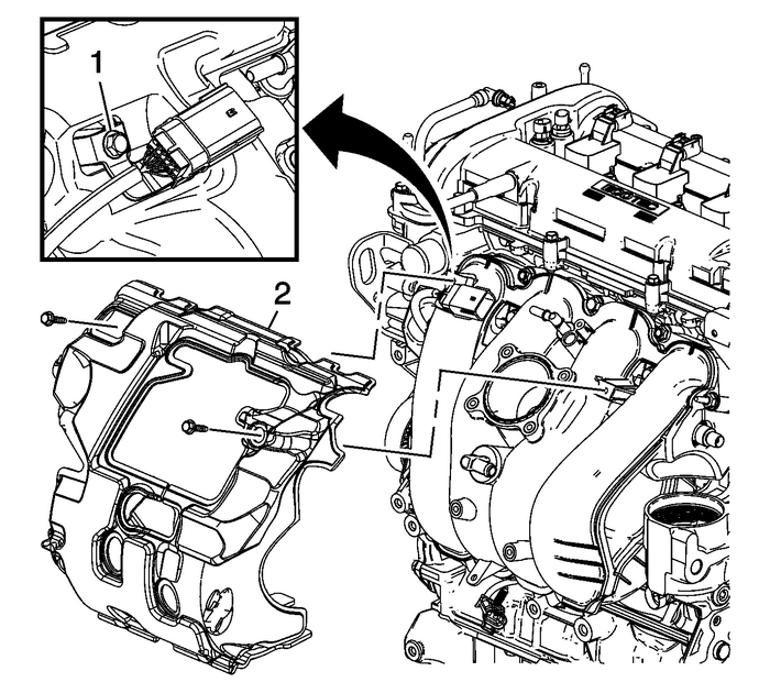
Install the intake manifold insulator-(2).Install the insulator bolt and tighten to 10-Y (89-lb-in).Install the fuel rail harness connector bracket-(1) to the intake manifold. Tightenthe bracket bolt to 10-Y (89-lb-in).
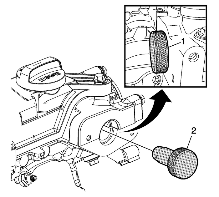
Note:The camshaft must be in the base circle position before the high pressure fuel pumpis installed.
Use the EN-48896 alignment gauge-(2) to ensure that the camshaft lobe is in the base circle position. At base circleposition, the tool will be flush with the head-(1).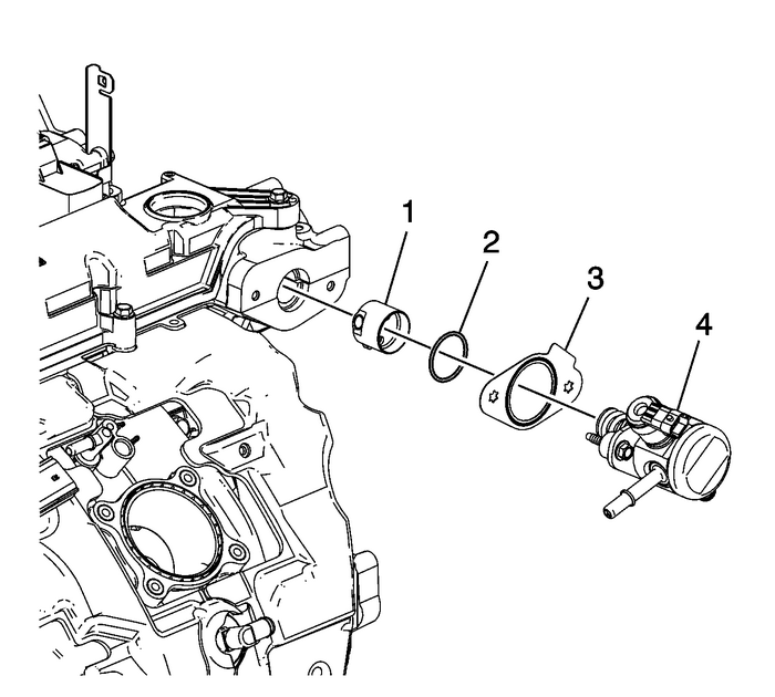
Lubricate the high pressure fuel pump cylinder head bore with 5W30 engine oil.
Note:Ensure that the high pressure fuel pump roller lifter is oriented properly, the camshaftis at base circle, and the number-1 piston is at top dead center-(TDC) on the exhauststroke. The distance from the mounting flange surface to the camshaft at base circleshould be 52-mm (2.05-in).
Lubricate the high pressure fuel pump roller lifter-(1) with 5W30 engine oil and installinto the cylinder head bore.Install a NEW fuel pump housing O-ring-(2) and gasket-(3).Note:Ensure the plastic bolt retainers are installed in the high pressure fuel pump mountingholes before installing.
Install the fuel pump assembly-(4).Start and hand-tighten the fuel pump assembly bolts evenly. Tighten the fuel pumpbolts evenly to 15-Y (11-lb-ft).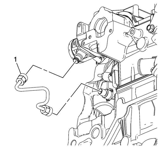
Install and hand-tighten both ends of the NEW high pressure fuel line-(1). Tightenthe high pressure fuel line fitting nuts to 30-Y (22-lb-ft).
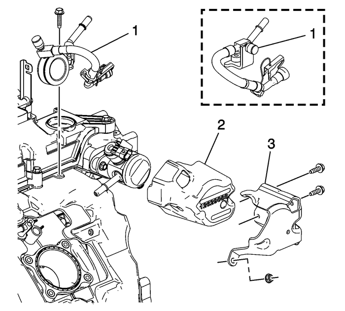
Install the fuel pump insulator-(2).
Note:The low pressure fuel pipe used is model dependent.
Install the low pressure fuel pipe assembly-(1).Install the fuel pump cover-(3) and nut. Tighten the nut to 10-Y (89-lb-in).Install the fuel pump cover bolts. Tighten the bolts to 10-Y (89-lb-in).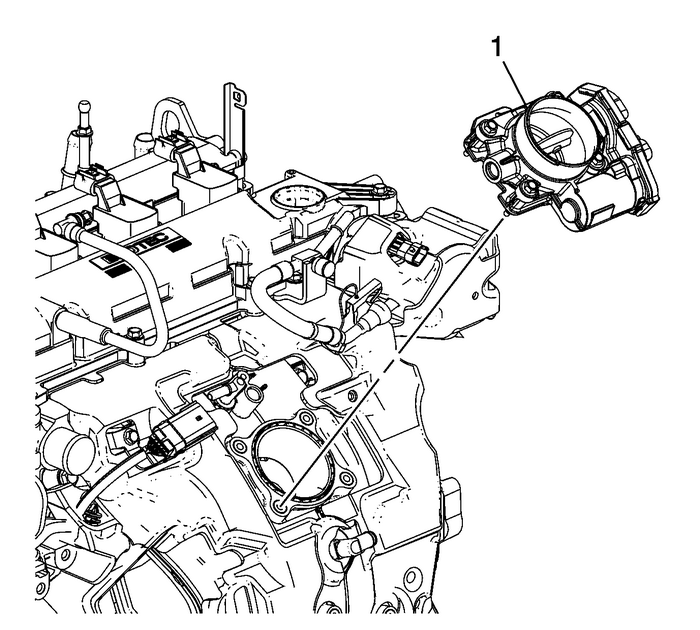
Install a new throttle body gasket.Install the throttle body-(1).Install the throttle body bolts and tighten to 10-Y (89-lb-in).
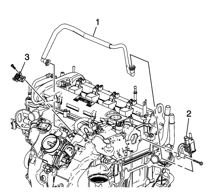
Install the MAP sensor-(3). Tighten the sensor bolt to 4-Y (35-lb-in).Install the EVAP canister valve-(2) and tighten to 25-Y (18-lb-ft).Install the EVAP canister valve tube-(1).
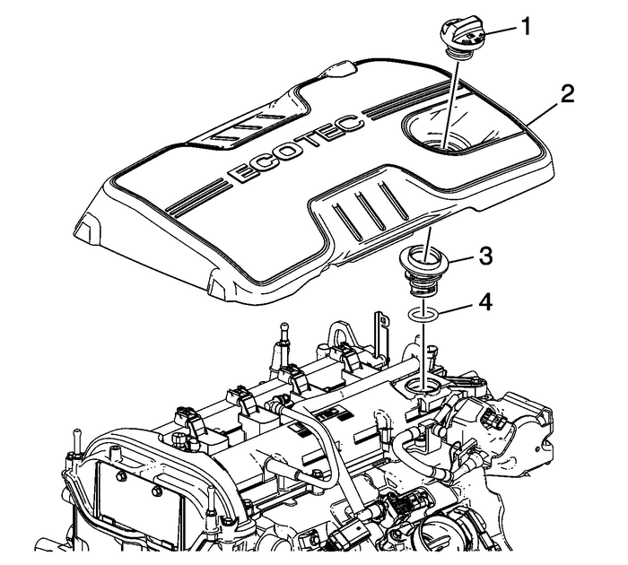
Install the O-ring and oil fill tube assembly-(3).Install the intake manifold cover-(2) onto the camshaft cover ball studs.Install the oil fill cap-(1).
 Crankshaft Sprocket Installation Engine Block Cylinder Block Crankshaft Sprocket
Special ToolsEN-48589Crankshaft Rotation SocketFor equivalent regional tools, refer toSpecial Tools.Ensure the crankshaft sprocket is installed with the timingmark-(1) visible.Install the crankshaft s ...
 Fuel Pump Installation Fuel System Fuel Pumps
Special Tools EN 48896 HP Fuel Pump Installation Alignment GaugeFor equivalent regional tools, refer toSpecial Tools.Note:The camshaft must be in the base circle position before the high pressure fuel ...
Other materials:
Passenger Compartment Air Filter
The filter removes dust, pollen, and other airborne irritants from outside air thatis pulled into the vehicle.The filter should be replaced as part of routine scheduled maintenance. SeeMaintenance Schedulefor replacement intervals. To find out what type of filter to use, seeMaintenance Replacement P ...
