Chevrolet Equinox Service Manual: Electronic Component Description Automatic Transmission Unit
Control Solenoid (W/Body and TCM) Valve Assembly

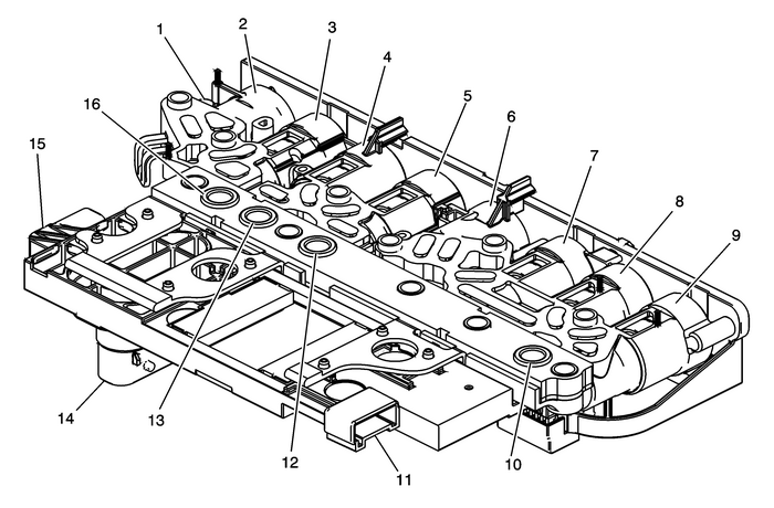
| (1) | Control Solenoid Valve Assembly X3(ISS) |
| (2) | ShiftSolenoid-1 |
| (3) | Pressure ControlSolenoid-3 (R1/456) |
| (4) | Pressure ControlSolenoid-5 (1234) |
| (5) | Torque Converter Clutch (TCC)Pressure Control Solenoid |
| (6) | ShiftSolenoid-2 |
| (7) | Pressure ControlSolenoid-2 (35R) |
| (8) | Pressure ControlSolenoid-4 (26) |
| (9) | Line Pressure ControlSolenoid |
| (10) | Transmission Fluid Pressure (TFP)Switch-5 (35R) |
| (11) | Control Solenoid Valve Assembly X2(IMS) |
| (12) | Transmission Fluid Pressure (TFP)Switch-3 (26) |
| (13) | Transmission Fluid Pressure (TFP)Switch-4 (456/R1) |
| (14) | Control Solenoid Valve AssemblyX1 |
| (15) | Control Solenoid Valve Assembly X4(OSS) |
| (16) | Transmission Fluid Pressure (TFP)Switch-5 (35R) |
The control solenoid (w/body and TCM) valve assembly containsthe following components:
Transmission control module-(TCM)Clutch pressure control solenoids-(Clutch PCSol)Shift solenoids-(SS)Line pressure control solenoid-(Line PCSol)Torque converter clutch pressure controlsolenoid-(TCC-PC Sol)Transmission fluid temperature sensor-(TFTSensor)TCM temperature sensorPower-up temperature sensorTransmission fluid pressure switches-(TFPSw)These components are not serviced separately. The controlsolenoid (w/body and TCM) valve assembly utilizes a lead-framesystem to connect these components electrically to the TCM. Nowires are used for these components. The control solenoid (w/bodyand TCM) valve assembly bolts directly to the lower and upper valvebody assemblies inside the transmission. The control solenoid(w/body and TCM) valve assembly connects to the engine harness20-way connector.
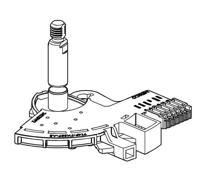
Manual Shift Detent Lever with Shaft Position SwitchAssembly (IMS)
The transmission shaft position switch assembly is a slidingcontact switch attached to the manual shaft detent lever assemblyinside the transmission case. The five inputs to the TCM from thetransmission manual shift shaft switch assembly indicate thetransmission gear selector lever position. This information is usedfor engine controls as well as determining the transmission shiftpatterns. The state of each input is available for display on thescan tool. The five input parameters represented areSignal-A, Signal-B, Signal-C,Signal-P (Parity) and Signal-N (P/N Start).The transmission shaft position switch assembly is connected to theControl Solenoid (W/Body and TCM) Valve Assembly via the ControlSolenoid ValveAssembly-X2-(IMS)-connector.
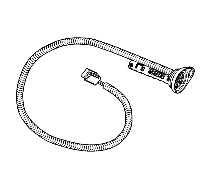
Input Speed Sensor (ISS)
The input speed sensor-(ISS) is a hall-effect typesensor. The ISS mounts to the transmission case cover assembly andconnects to the control solenoid (w/body and TCM) valve assemblythrough a wire harness and connector. The sensor faces the 3-5-Rclutch piston housing machined teeth surface. The sensor receives8.3–9.3-volts on the ISS/OSS Supply Voltagecircuit from the TCM. As the 3-5-R/4-5-6 clutch piston housingrotates, the sensor produces a signal frequency based on themachined surface of the 3-5-R/4-5-6 clutch piston housing. Thissignal is transmitted through the ISS signal circuit to the controlsolenoid (w/body and TCM) valve assembly. The TCM uses the ISSsignal to determine line pressure, transmission shift patterns,torque converter clutch-(TCC) slip speed and gear ratio.The input speed sensor (ISS) is connected to the Control Solenoid(W/Body and TCM) Valve Assembly via the Control Solenoid ValveAssembly-X3-(ISS)-connector.
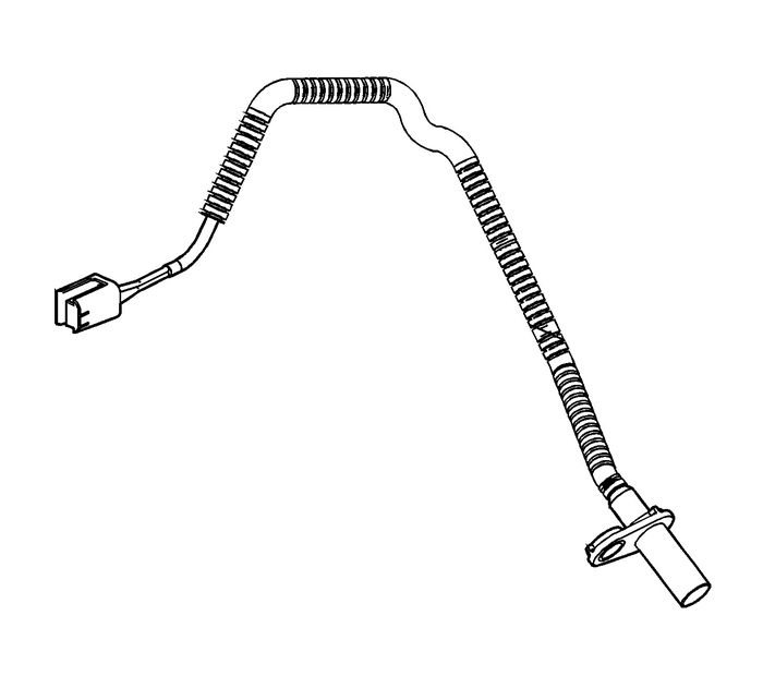
Output Speed Sensor (OSS)
The output speed sensor-(OSS) is a hall-effecttype sensor. The OSS mounts to the transmission case below thecontrol valve body assembly and connects to the control solenoid(w/body and TCM) valve assembly through a wire harness andconnector. The sensor faces the Park gear machined teeth surface.The sensor receives 8.3–9.3-volts on theISS/OSS supply voltage circuit from the TCM. As the frontdifferential transfer drive gear assembly rotates, the sensorproduces a signal frequency based on the machined surface of thePark gear. This signal is transmitted through the OSS signalcircuit to the TCM. The TCM uses the OSS signal to determine linepressure, transmission shift patterns, torque converterclutch-(TCC) slip speed and gear ratio. The output speedsensor (OSS) is connected to the Control Solenoid (W/Body and TCM)Valve Assembly via the Control Solenoid ValveAssembly-X4-(OSS)-connector.
 Engine Flywheel Cleaning and Inspection Flywheel/Flexplate
Clean the flywheel in solvent.Warning:Refer toSafety Glasses Warning.Dry the flywheel with compressed air.Inspect the flywheel for the following:Damaged ring gear teethStress cracks around theflywheel ...
 Control Solenoid (w/Body and TCM) Valve Assembly - Channel Plate Side Automatic Transmission Unit
Control Solenoid (w/Body and TCM) ValveAssembly-–-Channel PlateSidein.(2)Line(11)Actuator Feed Limit(12)PCS Line(13)PCS R1/456 Clutch(14)Shift Solenoid(18)PCS 35 Reverse Clutch(25)PCS 1234 Clutch(31 ...
Other materials:
Brake Fluid
The brake master cylinder reservoir
is filled with GM approved DOT 3
brake fluid as indicated on the
reservoir cap. See Engine
Compartment Overview for
the location of the reservoir.
Checking Brake Fluid
With the vehicle in P (Park) on a
level surface, the brake fluid level
should be betw ...
