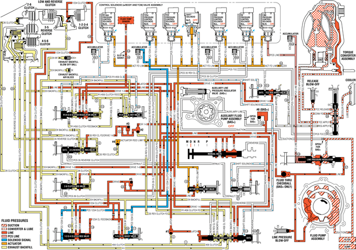
Chevrolet Equinox Service Manual: Drive Range, First Gear (Gen 2/Hybrid) Automatic Transmission Unit
As the vehicle speed increases, the transmission controlmodule (TCM) receives input signals from the automatic transmissioninput and output speed sensors, throttle position sensor and othervehicle sensors to determine the precise moment to de-energize or“turn OFF” the shift solenoid, and to commandOFF the normally-high R1/456 pressure control solenoid.
Low & Reverse Clutch ReleasesShift Solenoid
The shift solenoid is commanded OFF allowing shift solenoidfluid pressure to exhaust from the clutch select valve, the defaultoverride valve, and the TCC regulator apply valve.
Clutch Select Valve
Shift solenoid fluid is exhausted from the clutch selectvalve and clutch select valve spring force moves the valve to thereleased position. This allows R1 fluid pressure to pass throughthe valve into the exhaust backfill circuit. Drive fluid from themanual valve passes through the clutch select valve and enters thedrive 1-6 fluid circuit. Drive 1-6 fluid is routed to the R1/4-5-6clutch regulator valve, the 3-5-reverse clutch regulator valve, andthe TCC regulator apply valve.
Low and Reverse Clutch
Low and reverse clutch spring force moves the low and reverseclutch piston to release the low and reverse clutch plates andforce R1 fluid to exhaust from the case assembly. The exhausting R1fluid is routed to the clutch select valve where it enters theexhaust backfill circuit.
Fluid Pressure Directed in Preparation for a ShiftR1/456 Pressure Control (PC) Solenoid
The R1/456 PC solenoid is commanded OFF allowing PCS R1/456clutch fluid to exhaust from the R1/4-5-6 clutch regulator valveand the R1/4-5-6 clutch boost valve.
R1/4-5-6 Clutch Regulator Valve
R1/4-5-6 clutch regulator valve spring force moves the valveto the released position, allowing R1/456 clutch feed fluid toenter the exhaust backfill circuit, and drive 1-6 fluid to enterthe latch fluid circuit. Latch fluid is routed to the #1 ball checkvalve.
#1 Ball Check Valve
Latch fluid pressure seats the #1 ball check valve againstthe 456 clutch fluid circuit. Latch fluid is then directed to theclutch select valve. Latch fluid combines with clutch select valvespring force and holds the valve in this position during all sixforward gear ranges.
#2 Ball Check Valve
Drive 1-6 fluid pressure seats the #2 ball check valveagainst the 35 reverse clutch feed fluid passage, and is directedinto the 35 reverse clutch feed/drive 1-6 circuit. 35 reverseclutch feed/drive 1-6 fluid is routed to the #3 ball checkvalve.
#3 Ball Check Valve
35 reverse clutch feed/drive 1-6 fluid pressure unseats the#3 ball check valve and is directed to the 3-5-reverse clutchregulator valve.
Fluid Pressure Directed in Preparation for Torque ConverterClutch (TCC) ApplyTCC Regulator Apply Valve
Drive 1-6 fluid is routed to the TCC regulator apply valve inpreparation for TCC apply.
Drive Range, FirstGear-–-Gen 2/Hybrid
 Approximate Fluid Capacities Automatic Transmission Unit
Approximate Fluid CapacitiesApplicationSpecificationMetricEnglishSynthetic Lubricant– Transfer Case0.8-liter0.85-quart ...
 Drive Range, Sixth Gear Automatic Transmission Unit
As the vehicle speed increases, the transmission control module-(TCM) receives inputsignals from the automatic transmission input and output speed sensors, the throttleposition sensor and other vehicl ...
Other materials:
Front or Rear Side Door Lower Weatherstrip Replacement Doors
Front or Rear Side Door Lower Weatherstrip ReplacementCalloutComponent Name1Front and Rear Door Lower Weatherstrip Retainer(Qty:-17)ProceduresOpen both side doors on the side the weatherstrip is beingserviced.Use a suitable tool in the removal of the retainers.2Front and Rear Door Lower Weatherstrip ...
