Chevrolet Equinox Service Manual: Cylinder Head Replacement Engine Block Cylinder Head
Special ToolsJ 45059 Angle MeterEN-48953 Camshaft Actuator Locking ToolJ 38185 Hose Clamp PliersEN-48749 Timing Chain Retention Tool KitRemoval ProcedureDrain the cooling system. Refer toCooling System Draining and Filling.Remove the exhaust manifold. Refer toExhaust Manifold Replacement.Remove the intake manifold. Refer toIntake Manifold Replacement.Reposition the radiator surge tank air bleed hose clamp.Remove the radiator surge tank air bleed hose from the cylinder head.Reposition the radiator inlet hose clamp using the J 38185 hose clamp pliers.Remove the radiator inlet hose from the cylinder head.Disconnect all electrical connectors as necessary.Remove the spark plugs. Refer toSpark Plug ReplacementRemove the camshaft cover. Refer toCamshaft Cover Replacement.
Note:If the intake camshaft actuator is moving independently of the camshaft, this meansthe camshaft is not locked to the actuator. Rotate the camshaft counter-clockwisewhile the holding tool is installed and this will lock the camshaft to the actuator.
Rotate the crankshaft clockwise to install the EN-48953 camshaft actuator locking tool.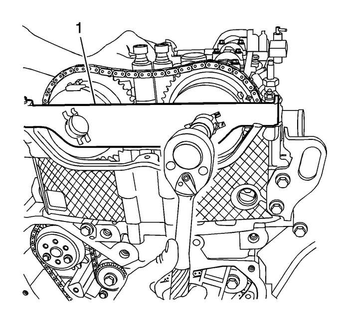
Install the EN-48953 camshaft actuator locking tool -(1).
Caution:Refer toFastener Caution.
Install the camshaft actuator tool and tighten bolts to 10-Y (89-lb-in).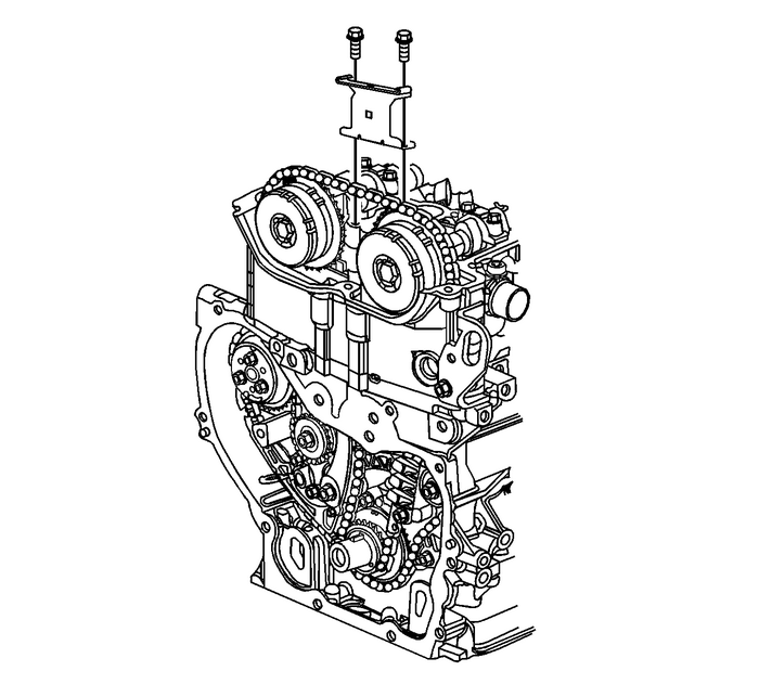
Remove the upper timing chain guide bolts and guide.Clean the timing chain and gears with solvent.
Note:Ensure the timing chain and the camshaft position actuators are marked for properassembly.
Mark the timing gear sprockets and the timing chain. It is recommended that the paintmarks are located in the 12-o'clock position.Loosen, but do not remove the intake and exhaust camshaft actuator bolts.Remove theEN-48953 camshaft actuator locking tool.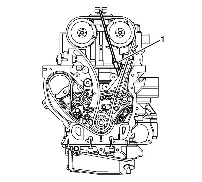
Note:Ensure the tips of the EN-48749 timing chain retention tool kit are fully engaged into the timing chain. The retention tool rod can be used on theback side of the chain to ensure the teeth from the retention tool are engaged.
Install the EN-48749 timing chain retention tool kit (1) to the intake side of the timing chain.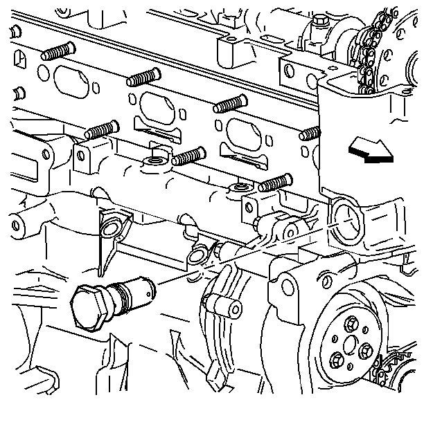
Remove the timing chain tensioner.
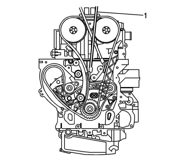
Note:The intake camshaft and actuator should not rotate during the removal or installation.
Install the EN-48749 timing chain retention tool kit (1) to the exhaust side of the timing chain.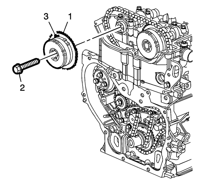
Remove and discard the exhaust camshaft actuator bolt-(2).Remove the exhaust cam actuator (3) from the exhaust camshaft while also removingthe actuator from the chain.
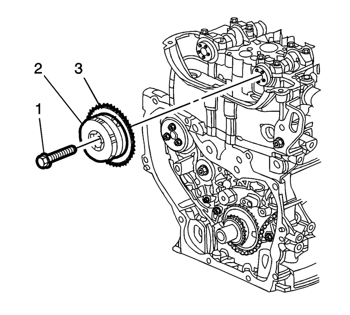
Remove and discard the intake camshaft actuator bolt-(2).Remove the intake camshaft actuator-(3) from the camshaft while also removing theactuator from the timing chain.
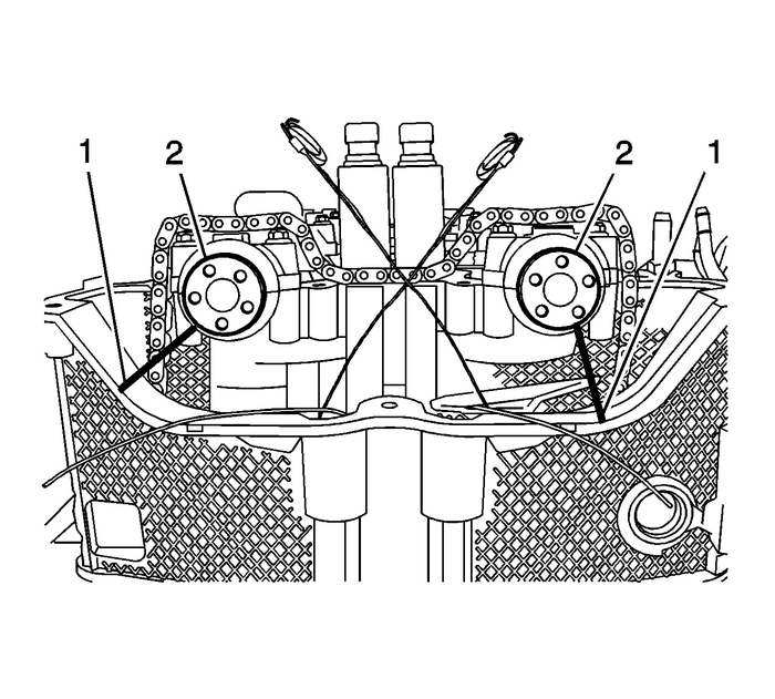
Note:If equipped with the following engine; LE5, LE9, LAT, LNF, LDK, LHU, LTD, LBN, or2010 LAF, ensure the intake camshaft notch is in the 5-o'clock position-and the exhaustcamshaft notch is in the 7-o'clock position.
Mark the cylinder head-(1) in relationship to the camshaft actuator notch is on thecamshaft-(2).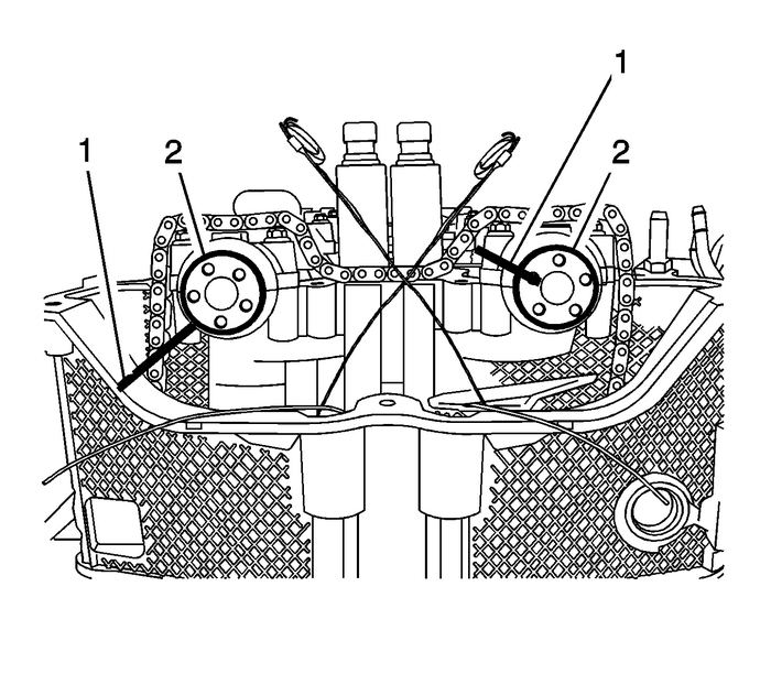
Note:If equipped with following engine; LAP, LE8, LEA, LUK , or 2011 LAF, ensure the intakecamshaft notch is in the 10 o'clock position and the exhaust camshaft notch is inthe 7 o'clock position.
Mark the cylinder head-(1) in relationship to the camshaft actuator notch is on thecamshaft-(2).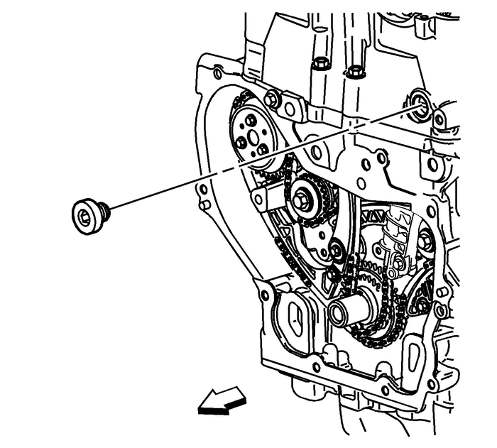
Remove the fixed timing chain guide access plug.Remove the upper fixed timing chain guide bolt.
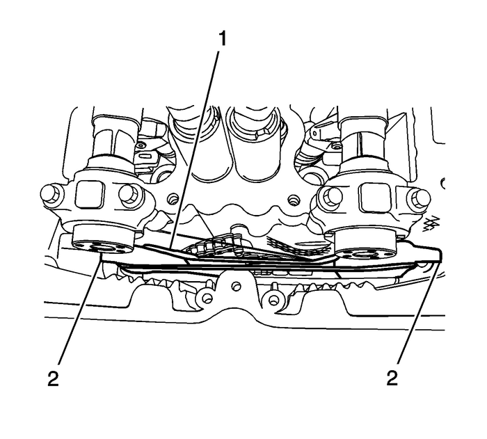
Note:The threaded rod from the timing chain retention tool can be used to help feed therubber band around the chain guides.
Install a rubber band-(1) around the top of the upper timing chain guides-(2) in orderto pull the guides together.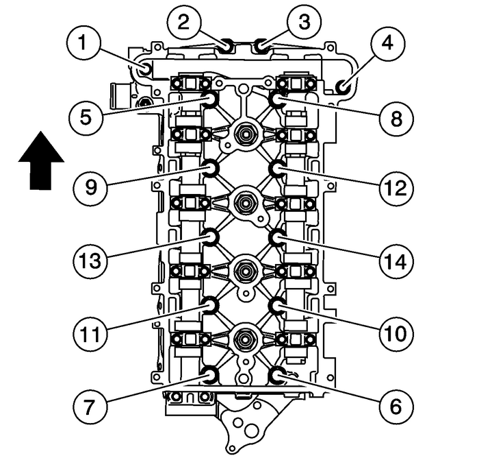
Remove the cylinder head bolts in the sequence shown. Discard the bolts.
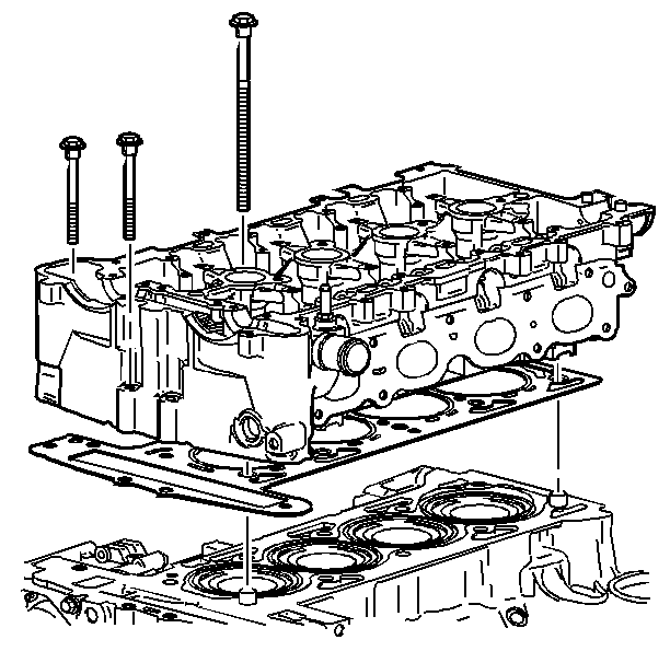
Note:A help of assistant maybe need for removal or installation of the cylinder head.
Remove the cylinder head.Remove the cylinder head gasket.Clean all of the gasket surfaces.Use the following steps when cleaning the cylinder head and cylinder block surfaces:Use a razor blade gasket scraper to clean the cylinder head and cylinder block gasketsurfaces. Do not scratch or gouge either surface.Note:DO NOT use any other method or technique to clean these gasket surfaces.
Use a NEW razor blade on the cylinder head and a NEW blade on the cylinder block.Note:Be careful not to gouge or scratch the gasket surfaces. DO NOT gouge or scrape thecombustion chamber surfaces. The feel of the gasket surface is important, not theappearance. There will be indentations from the gasket left in the cylinder head afterall of the gasket material is removed. These small indentations will be filled inby the NEW gasket.
Hold the razor blade as parallel to the gasket surface as possible.Clean the old sealer/lube and any dirt from around the bolt holes.Note:DO NOT use a tap to clean the cylinder head bolt holes.
Clean the bolts holes with a nylon bristle brush.When cleaning the cylinder head bolt holes use suitable commercial spray liquid solventand compressed air from an extended-tip blow gun in order to reach the bottom of theholes.If replacing the cylinder head, transfer all parts as necessary.Installation Procedure
Note:A help of assistant maybe need for removal or installation of the cylinder head.
Note:DO NOT use any sealing material.
Install the cylinder head gasket.Install the cylinder head.Install NEW cylinder head bolts.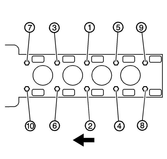
Install and tighten the cylinder head bolts in the sequence shown to 30-Y (22-lb-ft) plus an additional 155-degrees using the J 45059 angle meter.
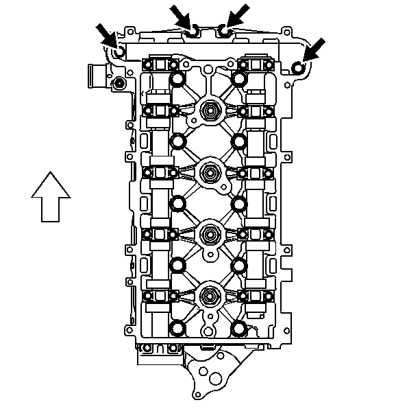
Install the NEW front cylinder head bolts and tighten the bolts to 35-Y (26-lb-ft).

Note:If equipped with the following engine; LE5, LE9, LAT, LNF, LDK, LHU, LTD, LBN, or2010 LAF, ensure the intake camshaft notch is in the 5-o'clock position-and the exhaustcamshaft notch is in the 7-o'clock position.
Ensure the cylinder head-(1) and the camshaft-(2) are correctly aligned.
Note:If equipped with following engine; LAP, LE8, LEA, LUK , or 2011 LAF, ensure the intakecamshaft notch is in the 10 o'clock position and the exhaust camshaft notch is inthe 7 o'clock position.
Ensure the cylinder head-(1) and the camshaft-(2) are correctly aligned.
Remove the rubber band-(1) from around the top of the upper timing chain guides-(2).Install the fixed guide bolt into the cylinder head and tighten to 12-Y (106-lb-in).

Apply sealant compound to thread and install the timing chain guide bolt access holeplug. Refer toAdhesives, Fluids, Lubricants, and Sealersfor the correct part number.Install the fixed timing chain guide access plug and tighten the plug to 75-Y (55-lb-ft).

Note:Ensure that the alignment mark made previously on the intake camshaft actuator isstill aligned properly with the mark on the timing chain. If the mark made previouslyon the intake camshaft actuator is not aligned properly, refer toCamshaft Timing Chain, Sprocket, and Tensioner Replacement.
Install the timing chain onto the intake camshaft actuator.Align the intake camshaft actuator alignment mark made previously with the timingchain mark and install the actuator onto the camshaft.Install a NEW intake camshaft actuator bolt-(2) until snug.
Remove the EN-48749 timing chain retention tool (1) from the intake side of the timing chain.

Note:Ensure that the alignment mark made previously on the exhaust camshaft actuator isstill aligned properly with the mark on the timing chain. The exhaust cam may haveto be rotated clockwise to install the exhaust actuator.
Install the timing chain onto the exhaust camshaft actuator.Align the exhaust camshaft actuator alignment mark made previously with the timingchain mark and install the actuator onto the camshaft.Install a NEW exhaust camshaft actuator bolt-(2) until snug.Remove theEN-48749 timing chain retention tool (1) from the exhaust side of the timing chain.Note:Failure to reset the chain tensioner will put excess tension on the chain, limitingthe chains life.
Reset and install the timing chain tensioner. Refer toTiming Chain Tensioner Replacement.
Install the EN-48953 camshaft actuator locking tool (1) to the actuators.Install the camshaft actuator locking tool bolts and tighten to 10-Y (89-lb-in).Tighten the NEW camshaft actuator bolt to 30-Y (22-lb-ft), plus an additional 100-degrees using the J 45059 angle meter.Release the tensioner by applying a counterclockwise rotational torque of 45-Y (33-lb-ft) to the harmonic balancer bolt .Remove the camshaft actuator locking tool, EN-48953 camshaft actuator locking tool.

Install the upper timing chain guide bolts and guide. Tighten the bolts to 10-Y (89-lb-in).Install the camshaft cover. Refer toCamshaft Cover Replacement.Install the spark plugs. Refer toSpark Plug Replacement.Connect all electrical connectors as necessary.Install the radiator inlet hose to the cylinder head.Position the radiator inlet hose clamp using the J 38185 hose clamp pliers.Install the radiator surge tank air bleed hose to the cylinder head.Position the radiator surge tank air bleed hose clamp.Install the exhaust manifold. Refer toExhaust Manifold Replacement.Install the intake manifold. Refer toIntake Manifold Replacement.Fill the cooling system. Refer toCooling System Draining and Filling.
 Radiator Outlet Hose Replacement (LFX) Engine Cooling Radiator
Special Tools J 38185 Hose Clamp PliersRemoval ProcedureRemove the intake manifold cover. Refer toIntake Manifold Cover Replacement.Drain the cooling system. Refer toCooling System Draining and Fillin ...
 Steering Gear Heat Shield Replacement (2.4L) Exhaust Exhaust Heat Shields
Steering Gear Heat Shield ReplacementCalloutComponent NamePreliminary ProcedureRaise and support the vehicle. Refer toLifting and Jacking the Vehicle.1Steering Gear Heat Shield Bolt (Qty:-3)Caution:Re ...
Other materials:
Heated Oxygen Sensor Replacement - Sensor 2 Engine Control Engine Control Sensors O2 Sensors
Heated Oxygen Sensor Replacement - Sensor 2CalloutComponent NamePreliminary ProcedureRaise and support the vehicle. Refer toLifting and Jacking the Vehicle.1Heated Oxygen SensorCaution:Do not remove the pigtail from either the heated oxygensensor (HO2S) or the oxygen sensor (O2S). Removing the pigta ...
