Chevrolet Equinox Service Manual: Rear Wheel Drive Shaft Outer Joint and Boot Replacement Wheels
Special ToolsJ-8059Snap Ring PliersJ-35910Drive Axle Boot Clamp Pliers
Note:The outer Constant Velocity Joint is not serviced separately.If the CV joint is found to have excessive wear or damaged, replacethe wheel drive shaft as an assembly.
Disassemble ProcedureRemove the wheel drive shaft from the vehicle. Refer toRear Wheel Drive Shaft Replacement.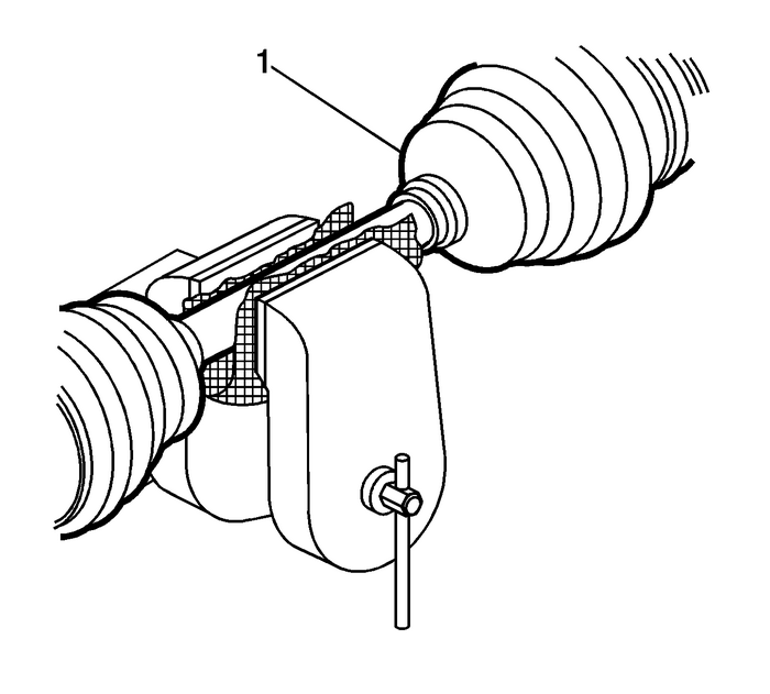
Install the wheel drive axle shaft in a soft jawedvice.
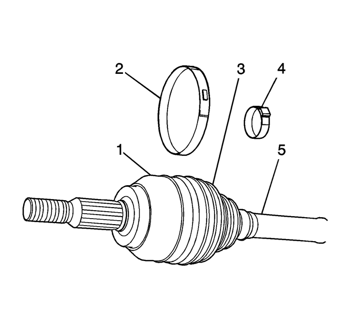
Caution:Do not cut through the wheel drive shaft inboard or outboardboot during service. Cutting through the boot may damage thesealing surface of the housing and the tripot or the constantvelocity joint bushing. Damage to the sealing surface may lead towater and dirt intrusion and premature wear of the constantvelocity joint.
Note:The following proceed is for the wheel drive shaft that havethe low profile boot clamp. If the wheel drive shaft is equippedwith the ear type boot clamp, proceed to step-6.
Using the appropriate tool, remove and discard the outer bootclamp-(2) from the CV joint boot-(3).Using a pair of side cutters, remove and discard the innerboot clamp-(4) from the CV jointboot-(3).Remove the cv joint boot-(3) from the CV jointhousing-(1).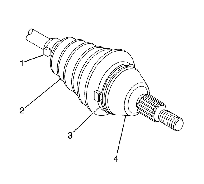
Using a pair of side cutters, remove and discard the outerboot clamp-(3) and the inner bootclamp-(1).Remove the CV joint boot-(2) from the CV jointhousing-(4).
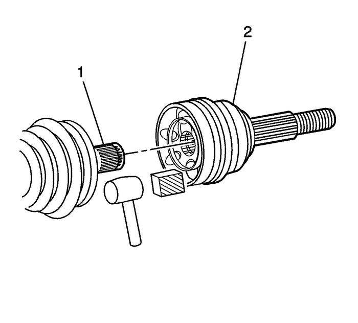
Using a hammer and a block of wood, remove the CVjoint-(2) from the wheel driveshaft-(1).
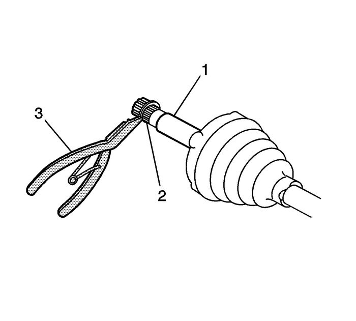
Using theJ-8059pliers, remove the retaining ring-(2) from the wheeldrive shaft.
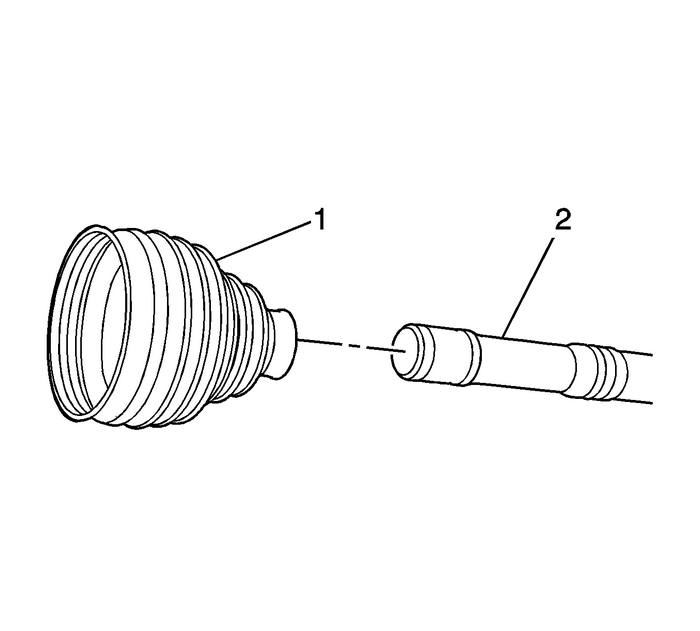
Remove the CV joint boot-(1) from the wheel driveshaft-(2).If the CV joint is found to be without any lubricant, havewater or any other contaminates in it. Replace the CV joint.Assemble Procedure

Position the boot and the clamp-(1) on the wheeldrive shaft-(2), DO NOT crimp.
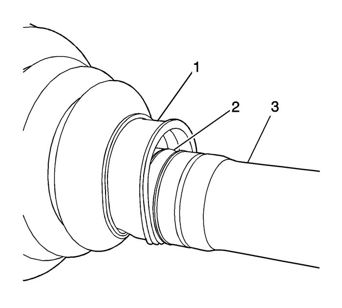
Ensure that the boot-(1) is properly seated in thegroove-(2) in the wheel driveshaft-(3).

Using theJ-8059pliers, install the retaining ring-(2) on the wheeldrive shaft-(1).
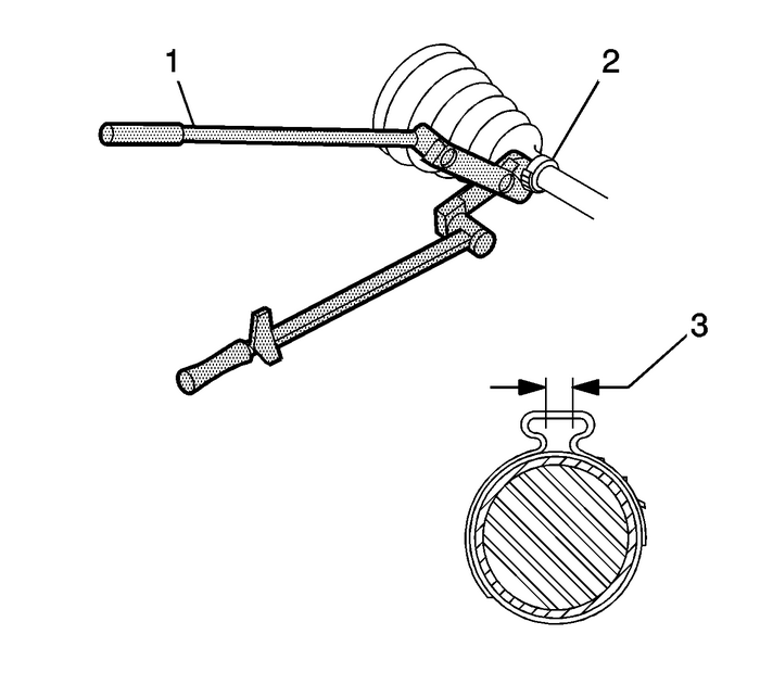
Using theJ-35910pliers-(1), close the boot clamp-(2) untilthe gap-(3) measures2.15-mm-(0.085-in).
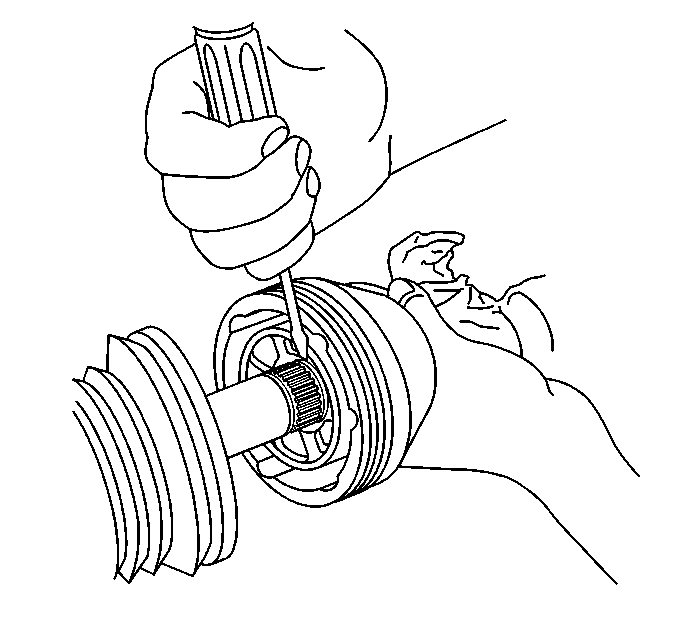
Using a small flat bladed screwdriver, compress the retainingring into the groove in the wheel drive shaft to allow installationof the inner CV joint on the wheel drive shaft.
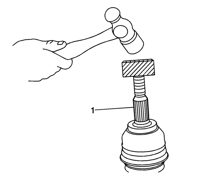
Note:The CV joint should just touch the inner retainingring.
Using a block of wood and a hammer, install the CV joint onthe wheel drive shaft-(1).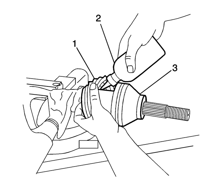
Place approximately half of the lubricant-(2)inside the CV boot-(1) and other half in the CVjoint-(3).Remove any excess lubricant on the CV joint housing or theboot.
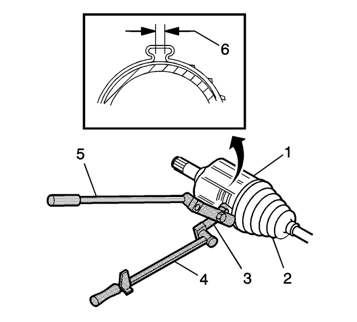
Using theJ-35910pliers-(3), torque or ratchet wrench-(4)and breaker bar-(5), close the boot clamp until thegap-(6) measures1.9-mm-(0.070-in).Move the CV joint in a circularmotion-4-to-5-times todistribute the lubricant.Remove the wheel drive shaft from the vise.Install the wheel drive shaft. Refer toRear Wheel Drive Shaft Replacement.
 Front Wheel Drive Shaft Inner Joint and Boot Replacement Wheels
Special ToolsJ-35910Drive Axle Seal Clamp PliersNote:The tripot assembly and the internal parts for the tripotassembly are not service. If the tripot assembly is found to haveexcessive wear or damaged ...
 Rear Wheel Drive Shaft Replacement Wheels
Special Tools J-42129 Wheel Hub RemoverFor equivalent regional tools, refer toSpecial Tools.Removal ProcedureRaise and support the vehicle. Refer toLifting and Jacking the Vehicle.Remove the tire and ...
Other materials:
Transmission Indicators and Messages Automatic Transmission Unit
The following transmission-related indicators andmessages may be displayed on the Instrument PanelCluster-(IPC). For a complete listing and description ofall vehicle indicators and messages, refer toIndicator/Warning Message Description and Operation."TRANSMISSION HOT IDLE ENGINE"This message is dis ...
