Chevrolet Equinox Service Manual: Piston and Connecting Rod Assemble Engine Block Cylinder Block Piston Assembly
Special Tools
EN-46745Piston Pin Retainer Remover andInstaller
For equivalent regional tools, refer toSpecial Tools.
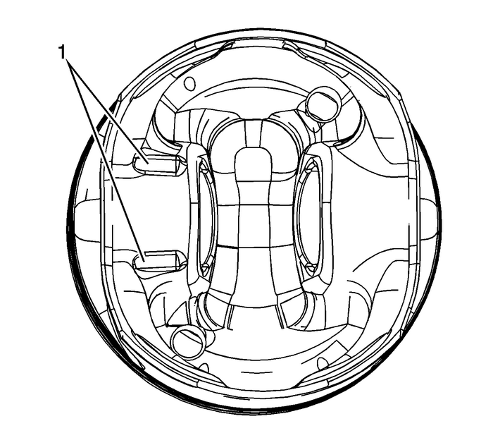
Note:Install the piston onto the connecting rod with the arrow ontop of the piston toward the front oriented toward the front of theengine.
Note:The cast boss-(1) can be in either or bothlocations depending on displacement.
The cast boss-(1), on the underside of the piston,must go to the rear of the block.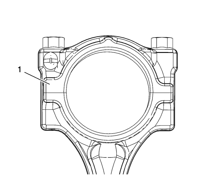
The larger feature-(1), at the split line locatedon one side of the connecting rod, must go to the front of theblock.
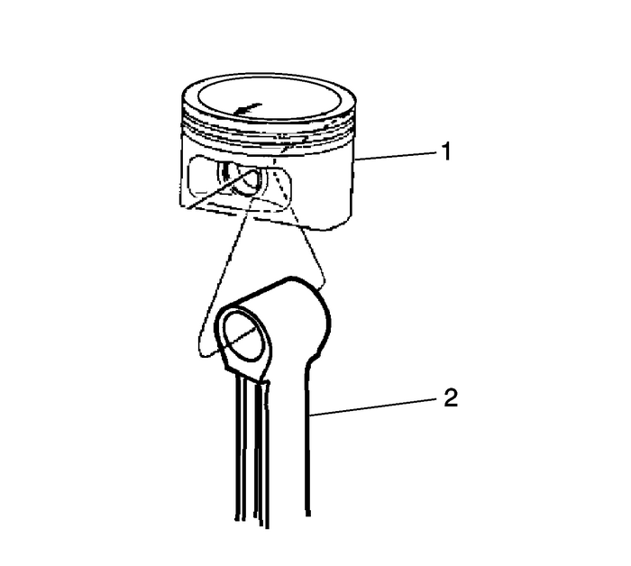
Assemble the connecting rod-(2) and thepiston-(1).
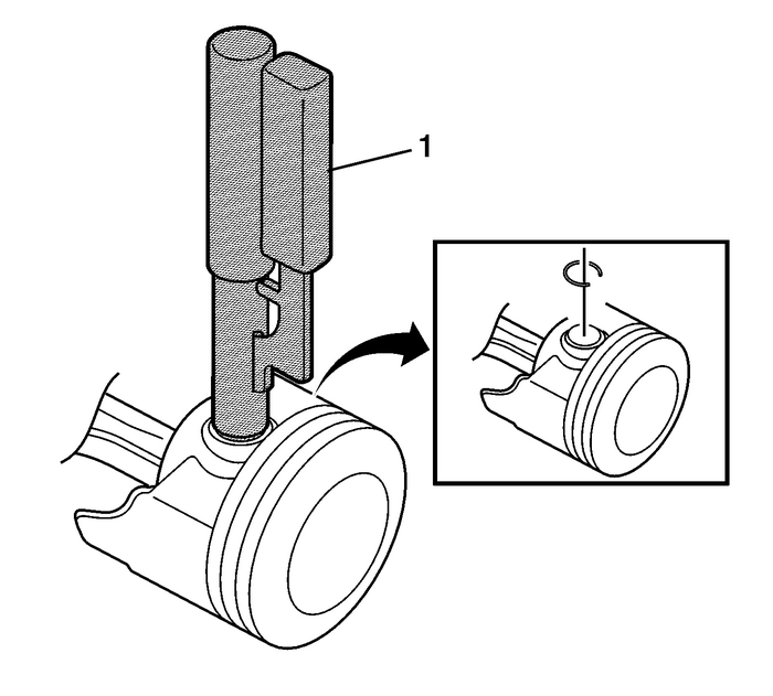
Caution:Install the piston pin retainers correctly in the retaininggroove during assembly in order to avoid engine damage.
Use the following procedure to assemble the piston pin andthe retainer:Coat the piston pin with oil.Install one side of one piston pin retainer into theretaining groove usingEN-46745installer. Rotate the retainer until it is fully seated in thegroove.Install the connecting rod and the piston pin.Push the piston pin until it bottoms in the previouslyinstalled retainer.
Install the second piston pin retainer, usingEN-46745installer-(1) .Ensure that the piston moves freely.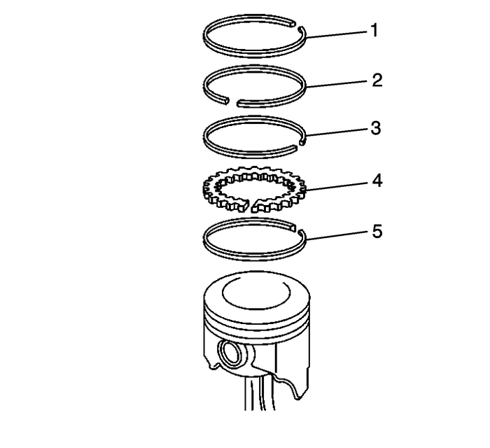
Caution:Use a piston ring expander to install the piston rings. Therings may be damaged if expanded more than necessary.
Install the following components of the oil control ringassembly (bottom ring):The expander-(5)The lower oil control ring-(4)The upper control ring-(3)Install the lower compression ring-(2). Place themanufacturer's mark facing up.Install the upper compression ring-(1). Piston and Connecting Rod Disassemble Engine Block Cylinder Block Piston Assembly
Special ToolsEN-46745Piston Pin Clip Remover/InstallerFor equivalent regional tools, refer toSpecial Tools.Caution:You must use a piston ring expander to remove and install thepiston rings. Only expan ...
 Piston and Connecting Rod Disassemble Engine Block Cylinder Block Piston Assembly
Special ToolsEN-46745Piston Pin Retainer Remover andInstallerFor equivalent regional tools, refer toSpecial Tools.Warning:Handle the piston carefully. Worn piston rings are sharp andmay cause bodily i ...
Other materials:
Backup Lamp Bulb Replacement (Terrain) Lighting Exterior Lighting Backup Lamp
Backup Lamp Bulb ReplacementCalloutComponent NamePreliminary ProcedureRemove the tail lamp applique. Refer toTail Lamp Applique Replacement.1Back Up BulbWarning:When working with any type of glass or sheet metal withexposed or rough edges, wear approved safety glasses and gloves inorder to reduce th ...
