Chevrolet Equinox Service Manual: Intake Manifold Replacement Intake and Forced Induction Intake Manifold
Removal ProcedureRecover the A/C system. Refer toRefrigerant Recovery and Recharging.Relieve the fuel system pressure. Refer toFuel Pressure Relief.Remove the air cleaner outlet duct. Refer toAir Cleaner Assembly Replacement.
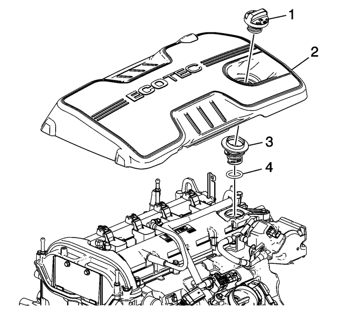
Caution:Never attempt to remove the intake manifold from a hotengine, allow the engine to cool to ambient temperature. The intakemanifold can be damaged if it is removed when the engine ishot.
Remove the oil fill cap-(1).Remove the intake manifold cover-(2).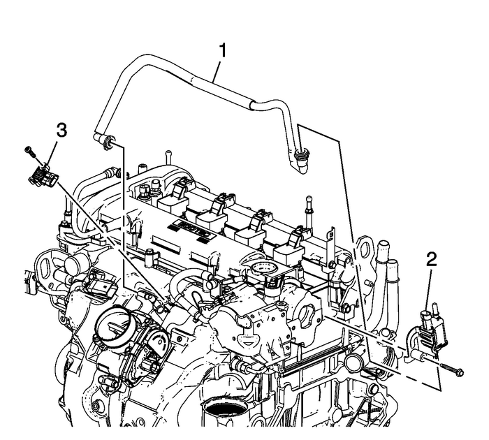
Remove the evaporative-(EVAP) emission canister valve tube-(1) from the intake manifoldand reposition.Remove the MAP sensor-(3) electrical connector.
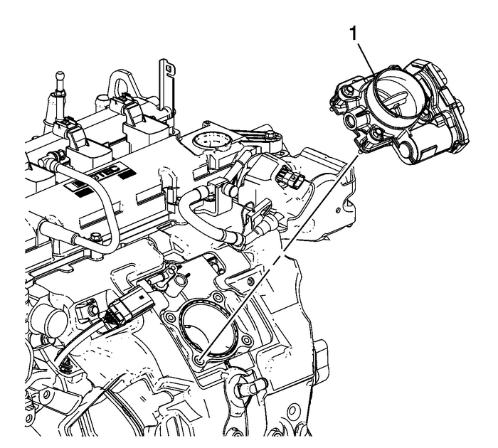
Remove the throttle body-(1). Refer toThrottle Body Assembly Replacement.
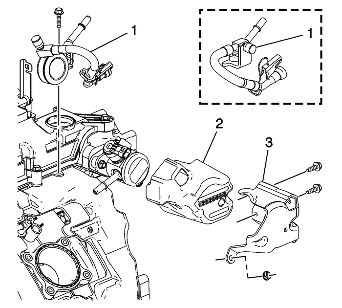
Remove the fuel pump cover-(3) and insulator-(2). Refer toFuel Pump Cover Replacement.
Note:The low pressure fuel pipe used is model dependent.
Disconnect and reposition the low pressure fuel feed pipe from the fuel pump. RefertoMetal Collar Quick Connect Fitting Service.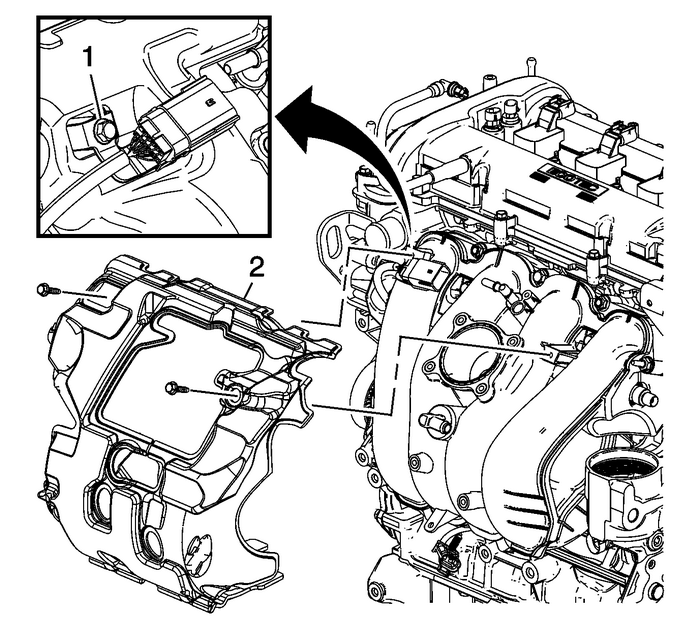
Remove the fuel rail harness connector bracket bolt-(1) and intake manifold insulatorbolt.Remove the intake manifold insulator-(2).
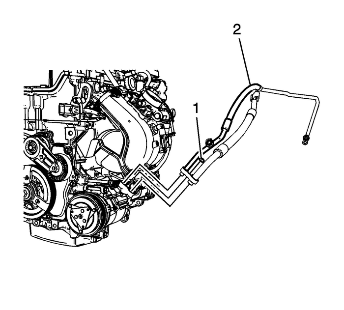
Remove the A/C line nut (1) and line (2) from the compressor and reposition the lineto the side.
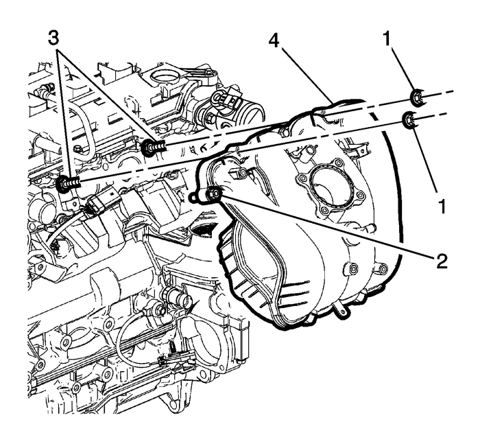
Note:Removing studs allows the intake manifold to be removed without removing the fuelpump.
Remove the intake manifold retaining nuts-(1), studs-(3), and bolts-(2).Remove the intake manifold-(1).Disconnect electrical connectors as necessary.Transfer parts as necessary.If reusing the intake manifold, clean and inspect as necessary. Refer toIntake Manifold Cleaning and Inspection.Installation Procedure
Position the intake manifold-(4) and hand start the bolts-(2).
Caution:Refer toFastener Caution.
Install the intake manifold studs-(3) and tighten to 15-Y (11-lb-ft).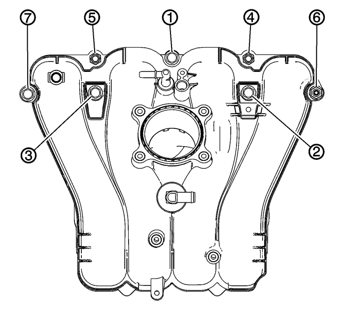
Tighten the bolts and nuts in sequence to 25-Y (18-lb-ft).

Install the intake manifold insulator-(2).Install the insulator bolt and tighten to 10-Y (89-lb-in).Install the fuel rail harness connector bracket-(1) to the intake manifold. Tightenthe bracket bolt to 10-Y (89-lb-in).

Install new seal washers to the compressor hose. Refer toAir Conditioning System Seal Replacement.Install the compressor hose (2) to the compressor.Install the compressor hose nut (1) to the compressor and tighten the nut to 22-Y (16-lb-ft).Connect the engine harness electrical connector as necessary.

Install the fuel pump insulator-(2) and cover-(3). Refer toFuel Pump Cover Replacement.
Note:The low pressure fuel pipe used is model dependent.
Install the low pressure fuel pipe assembly-(1).
Install a new throttle body gasket.Install the throttle body-(1). Refer toThrottle Body Assembly Replacement.

Install the EVAP canister valve tube-(1).Connect the MAP sensor electrical connector.

Install the intake manifold cover-(2) onto the camshaft cover ball studs.Install the oil fill cap-(1).Recharge the A/C system. Refer toRefrigerant Recovery and Recharging.Install the air cleaner assembly. Refer toAir Cleaner Assembly Replacement.
 Engine Oil and Oil Filter Replacement Engine Lubrication Oil Filter
Removal ProcedureRaise and support the vehicle. Refer toLifting and Jacking the Vehicle.Place a drain pan under the oil pan drain plug.Remove the oil pan drain plug. Allow the oil to draincompletely.C ...
 Direct Fuel Injector Replacement Fuel System Injectors
Removal ProcedureRelieve the high side fuel system pressure. Refer toFuel Pressure Relief.Note:The fuel injectors have an alignment feature, note theposition of the injectors alignment for installatio ...
Other materials:
Transmission Fluid Pump Cleaning and Inspection Automatic Transmission Unit
Transmission Fluid Pump Cleaning and InspectionCalloutComponent NameCaution:After cleaning the transmission components, allow to air dry.Do not use cloth or paper towels in order to dry any transmissioncomponents. Lint from the towels can cause componentfailure.Caution:Do not reuse cleaning solvents ...
