Chevrolet Equinox Service Manual: Front Seat Heater Kit Installation
Installation Instructions Part Number
19213668
1 | 1 | Passenger Seat Foam / Suppression / Heat Mat Assembly |
2 | 1 | Drivers Seat Back Heat Pad |
3 | 1 | Drivers Seat Cushion / Heat Pad |
4 | 1 | Passengers Seat Back Heat Pad |
5 | 1 | Electronic Module |
6 | 1 | Heated Seat Switch |
7 | 2 | Extension Harness |
8 | 1 | Power Jumper Harness |
9 | 1 | Switch Harness |
10 | 1 | Hardware Kit (Wire Ties, 1 Small Pice of Dual Sided Tape, 1 Large Pice of Dual SidedTape, Alcohol Swab, Switch Template and Switch Bezel) |
11 | 1 | Installation Instructions |
Note:Unless directed otherwise, the ignition and start switch must be in the OFF or LOCKposition, and all electrical loads must be OFF before servicing any electrical component.Disconnect the negative battery cable to prevent an electrical spark should a toolor equipment come in contact with an exposed electrical terminal. Failure to followthese precautions may result in personal injury and/or damage to the vehicleor its components.
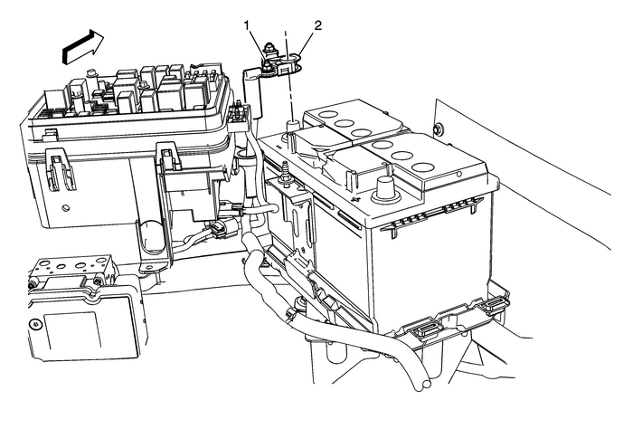
Turn on the radio and record all of the radio station presets.Turn off all lamps and accessories.Turn the ignition switch to the OFF position, and remove the ignition key.Loosen the negative battery cable terminal nut-(1).Remove the negative battery cable clamp-(2) from the negative battery terminal.Remove Passenger Seat Belt from PretensionerDisable the SIR system.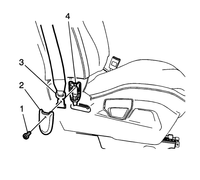
Remove the seat belt pretensioner bolt-(1) from passengers seat assembly using a T-30.Remove pretensioner outer cover-(2).Remove passengers seat belt-(3) from pretensioner-(4).Remove Passenger Front Seat
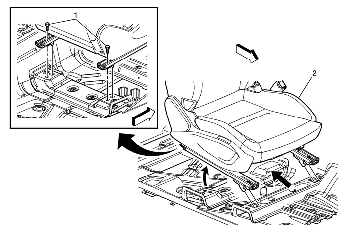
Remove the front seat mounting fasteners-(1) on the rear seat frame using a T-40.Disconnect the front seat and pretensioner electrical connector, and passenger presencesystem connector.With the aid of an assistant, tilt the rear of the seat-(2) upward, and then liftingand pulling the seat rearwards to disengage the front hooks from the floor.Remove Passenger Seat Outer Finish Cover
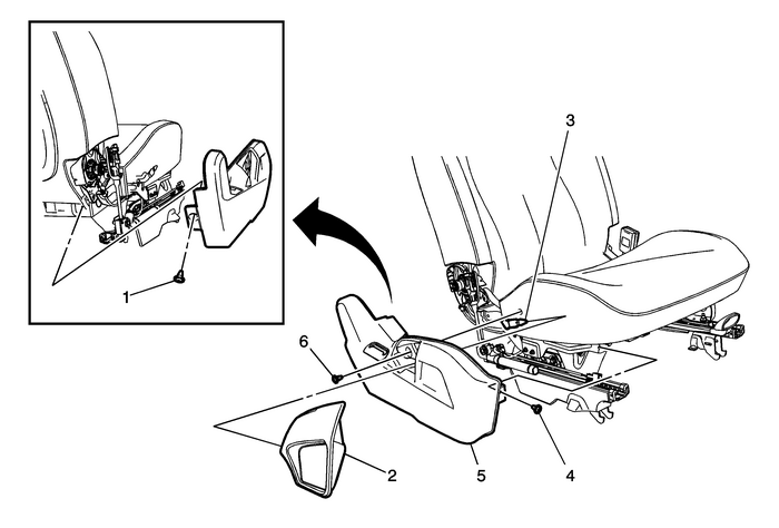
Note:Use a flat-bladed tool to release the recliner handle-(2) from the recliner bracket-(3).
Pull upward on the recliner handle-(2) in a north and south direction, without recliningthe seat back.Remove the seat belt inner pretensioner cover.Remove the outer screw-(6).Remove the front screw-(4).Remove the rear screw-(1).Disconnect electrical connectors from the seat outer finish cover, if equipped.Remove the seat outer finish cover-(5) by pulling upward near the retainer clip locations.Remove Passenger Seat Inner Finish Cover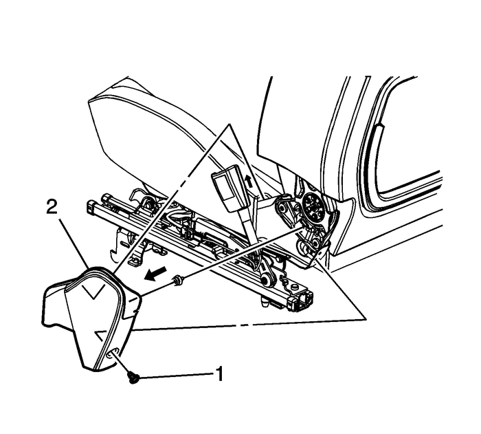
Remove the screw-(1).Firmly grasp the top of the inner finish cover-(2), pull upward and then outboardto disengage the inner finish cover from the seat cushion frame.Remove Passenger Seat Cushion Cover and Pad
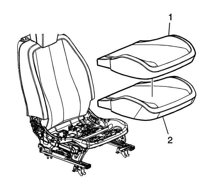
Unhook seat cushion trim cover-(1) from the seat frame.Remove the J-strips from the seat frame.Remove seat cushion-(2) and seat cushion trim cover-(1) from seat frame as an assembly.Remove seat cushion trim cover-(1) from the seat cushion-(2) by pulling on cover-(1)to release Velcro.Passenger Seat Cushion and Heat Pad Installation
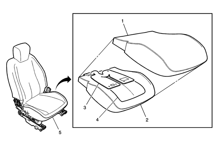
Reassemble the seat cushion trim cover-(1) to the new foam assembly-(2) from kit containingheat mat-(4) and suppression mat-(3) by pushing at Velcro ant attachment locations.Install seat foam assembly-(5) to seat frame.Passenger Seat Back Cushion Heat Pad Installation
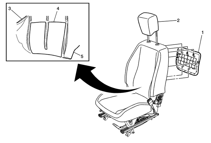
Pull the finish panel-(1) rearward at the bottom edge first to disengage the lowerretainers.Move the finish panel -(1) and side clips to one side to disengage the panel fromthe seat frame.Slide the finish panel-(1) downward to release the upper hooks from the seat backcushion pad support wire.Raise the front seat head restraint-(2) to the full upward position.
Note:Do not remove the head restraint.
Pull the front seat back cushion cover-(3) over the seat foam-(5) toward the frontside inflatable restraint module.Remove the J-channels from the seat back frame.Unhook seat back cushion trim cover from seat back cushion by pulling to release VelcrofastenersPull the seat back cushion trim cover over the seat back cushion toward the frontside inflatable restraint module - leaving cover attached at the top and at the frontside inflatable restraint module.Assemble heat pad-(4) to seat back cushion-(5) and route wire pigtail.Reassemble seat back cushion trim cover-(3) to seat back cushion-(5) by pushing atVelcro at attachment locations.Reassemble seat trimReassemble seat inner and outer trim panels.Reinstall seat back finish panel.Driver Seat Cushion and Seat Back Heat Pad InstallationNote:Heat pad installation process is exactly the same except there is no air bag suppressionpad in the driver's seat. There is no foam assembly for the driver's side in the kit,only heat pad.
Assembly heat pad to the driver's side bottom foam cushion and route wire pigtail.Install the seat back heat pad.Note:Seat back heat pad installation is the same as the passenger side.
Remove Instrument Panel Lower Extension Accessory Bezel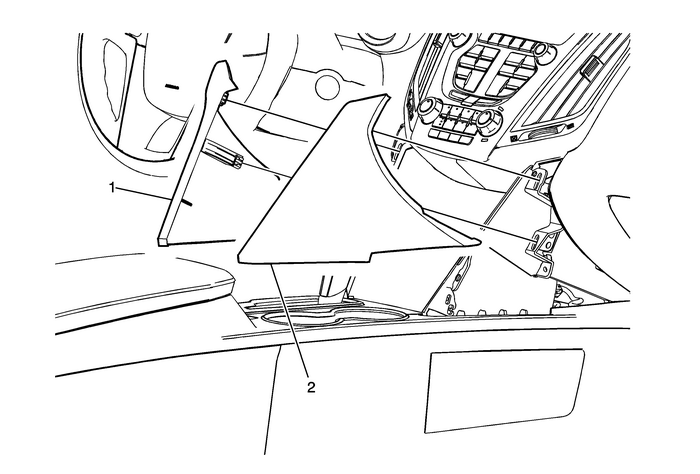
Using a flat-bladed plastic trim tool, release the retainer clips securing the left-(1)and right-(2) instrument panel lower extensions to the instrument panel.
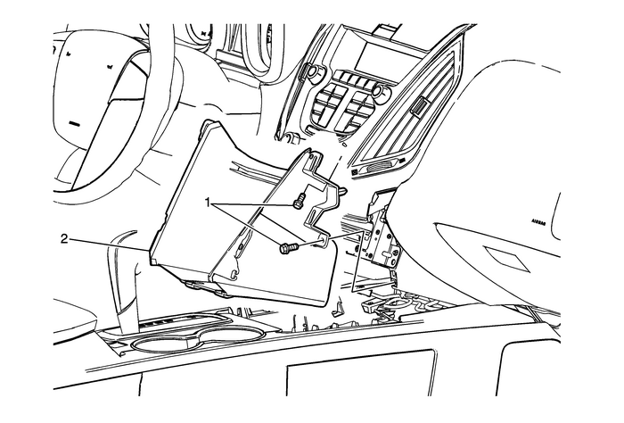
Remove the two fasteners-(1) from each side of the instrument panel lower extensionaccessory bezel-(2).Remove the lower extension accessory bezel-(2) and disconnect electrical connectors.Install Heated Seat Switch
Note:Heated seat switch assembly with ribbon cable is a precision electronic component,and forcefully pulling or twisting of this component during installation should beavoided.
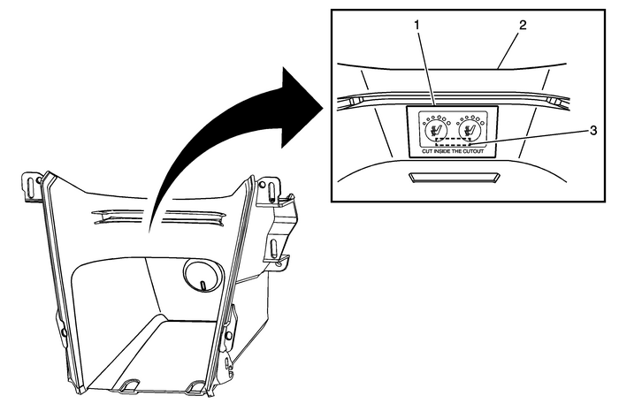
Using the switch template-(1) from kit, tape the template in the center of the lowerextension accessory bezel-(2) (below CD opening) and cut slot-(3) for switch connector.
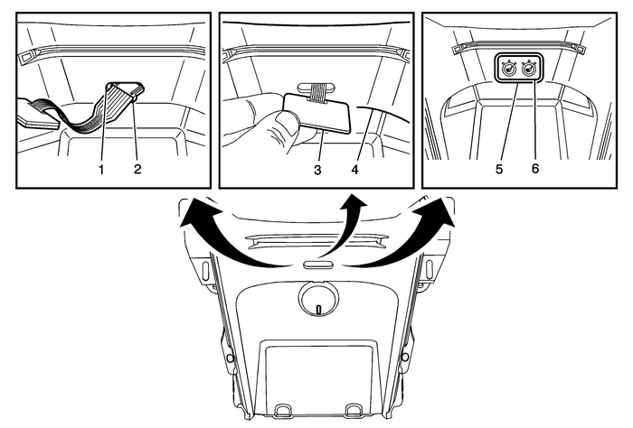
Note:After cutting slot in lower extension accessory bezel, apply alcohol swab (from kit)to bezel to clean before installing switch.
Route switch connector-(2) through slot-(1) in lower extension accessory bezel.Remove paper backing-(3) from switch and attach to lower extension accessory bezel-(4).Apply switch bezel-(5) (from kit) over switch-(6).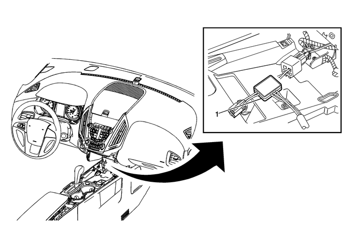
Install power harness jumper-(1) (T-shaped harness) between the aux outlet connectorand route remaining branch through lower console (forward most hole on passenger side).
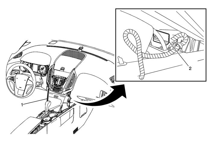
Position lower extension accessory bezel-(1) to vehicle, connect switch jumper harness-(2)to switch pigtail, apply small piece of double sided tape to connector, and secureto lower extension accessory bezel.Reinstall lower extension accessory bezel-(1).Connect LED connector.Connect auxiliary outlet to T-shaped harness.Secure the four bolts on lower extension accessory bezel-(1) to instrument panel.Install Heated Seat Electronic Module Assembly
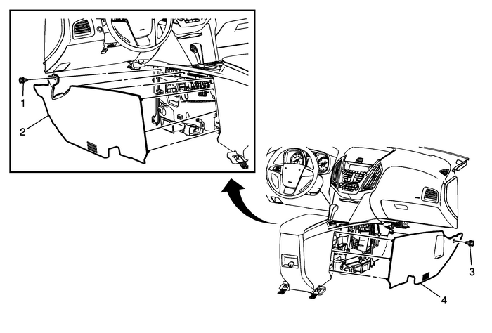
Remove left-(2) and right-(4) console side trim panels, by removing the push-in retainers-(1),(3)and disengage the clips.
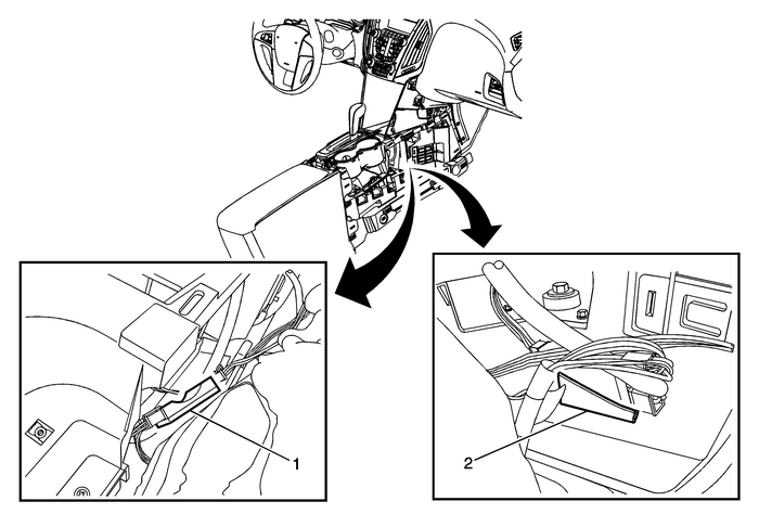
Place module-(1) in console (in front of cup holder) to connect electrical connectorsand install.Connect switch jumper harness to largest connector on module - connector #5.Connect power harness to module - connector #4.Connect driver side extension harness to module - connector #1.
Note:Route driver side extension harness through console to driver's side of console.
Connect passenger side extension harness to module - connector #3.Install heated seat module with large piece of double sided tape-(2) in console (infront of cup holder).Reinstall console side trim panels by installing the push-pins and engaging clips.Driver Accessory Seat Wire Harness and Seat InstallRoute driver side extension harness rearward along console, then to driver side seatwiring.Tuck wiring under console side panel out of sight.Position driver seat in vehicle and tilt seat forward.Connect accessory extension harness to green and black heat pad connectors in seatand reconnect seat/body in-line connectors.Reinstall previously removed seat trim.Caution:Use the correct fastener in the correct location. Replacementfasteners must be the correct part number for that application.Fasteners requiring replacement or fasteners requiring the use ofthread locking compound or sealant are identified in the serviceprocedure. Do not use paints, lubricants, or corrosion inhibitorson fasteners or fastener joint surfaces unless specified. Thesecoatings affect fastener torque and joint clamping force and maydamage the fastener. Use the correct tightening sequence andspecifications when installing fasteners in order to avoid damageto parts and systems.
Install the drivers seat with the two previously removed fasteners (rear of seat frame).Tighten
Tighten the driver seat fasteners to 45-Y (33-lb-ft).Install seat belt to belt pretensioner.Install belt pretensioner cover and bolt.
Tighten
Tighten belt pretensioner bolt to 45-Y (33-lb-ft).Wire tie excess extension harness length to seat wiring, making sure there is enoughwiring for seat travel.Passenger Accessory Seat Wire Harness and Seat InstallRoute passenger side extension harness rearward along console, then to passenger sideseat wiring.Tuck wiring under console side panel out of sight.Position passenger seat in vehicle and tilt seat forward.Connect accessory extension harness to green and black heat pad connectors in seatand reconnect seat/body in-line connectors.Reinstall previously removed seat trim.Install the passengers seat with the two previously removed fasteners (rear of seatframe).
Tighten
Tighten the passenger seat fasteners to 45-Y (33-lb-ft).Install seat belt to belt pretensioner.Install belt pretensioner cover and bolt.
Tighten
Tighten belt pretensioner bolt to 45-Y (33-lb-ft).Wire tie excess extension harness length to seat wiring, making sure there is enoughwiring for seat travel.Final StepsReconnect negative battery cable.Enable the SIR system.Perform the Passenger Presence System Preload Test.Turn ignition key to run position and test heated seats.Push driver and passenger heated seat switches and cycle through the three LED indicators.3-LED's = High2-LED's = Med1-LED = Low0-LED = Off
 Multimedia Player Interface Module Package Installation (Installation Instructions)
Installation Instructions Part Number19211506Kit ContentsQtyDescription1Instrument Panel (I/P) Harness1Console Harness1Installation Instructions1PDIM Module1USB/Audio Combo Auxiliary (AUX) Jack1USB Co ...
 Front Fog Lamp Package Installation
Installation Instructions Part Number23206778Kit ContentsQtyDescription1Left Fog Lamp Assembly1Right Fog Lamp Assembly1Left Fog Lamp Bezel1Right Fog Lamp Bezel1Steering Column Switch6Tie Straps1Fog La ...
Other materials:
Special Tools
IllustrationTool Number / DescriptionEL-25070EL-38125-5AEL-38125-5J-38125-5AHeat Gun 500–700 FEL-35616KM-609Tyco Electronic Tool (5–1579007–3)Terminal Test Probe KitEL-35616-200KM-J-34142–BTest Light– Probe KitEL-35616-20FKM-963Fused Jumper WireEL-38125–10 (Non-North America)EL-38125–E ...
