Chevrolet Equinox Service Manual: Engine Replacement
Special Tools
J-38185Hose Clamp Pliers
For equivalent regional tools, refer toSpecial Tools.
Removal ProcedureRelieve the fuel pressure. Refer toFuel Pressure Relief.Remove negative battery cable from engine block. Refer toBattery Negative Cable ReplacementDisconnect the negative battery cable. Refer toBattery Negative Cable Disconnection and Connection.Remove the intake manifold cover. Refer toIntake Manifold Cover Replacement.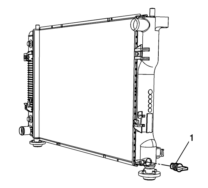
Drain-(1) the cooling system. Refer toCooling System Draining and Filling.Drain the engine oil. Refer toEngine Oil and Oil Filter Replacement.Remove the air cleaner assembly. Refer toAir Cleaner Assembly Replacement.Remove the battery tray. Refer toBattery Tray Replacement.
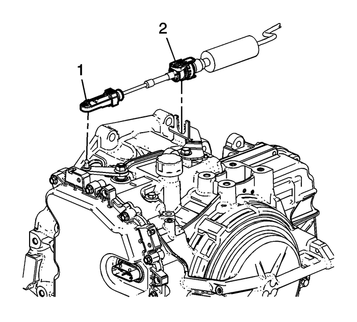
Disconnect the range selector cable end-(1) fromthe range selector lever.Disconnect the range selector cable-(2) from therange selector cable bracket.Disconnect the wiring harness from the underhood junctionblock. refer toAccessory Wiring Junction Block Replacement.Remove battery hold down retainer bracket.Disconnect right side inline electrical connector.
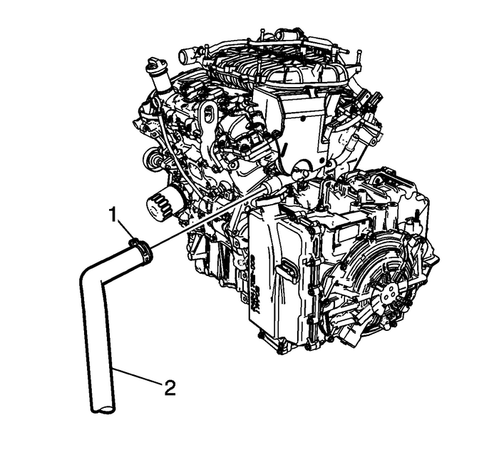
Disengage tension on the radiator outlet hose clamp (1) atthe engine usingJ-38185pliers.
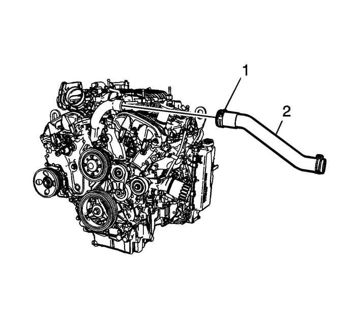
Remove the radiator outlet hose (2) from the engine.
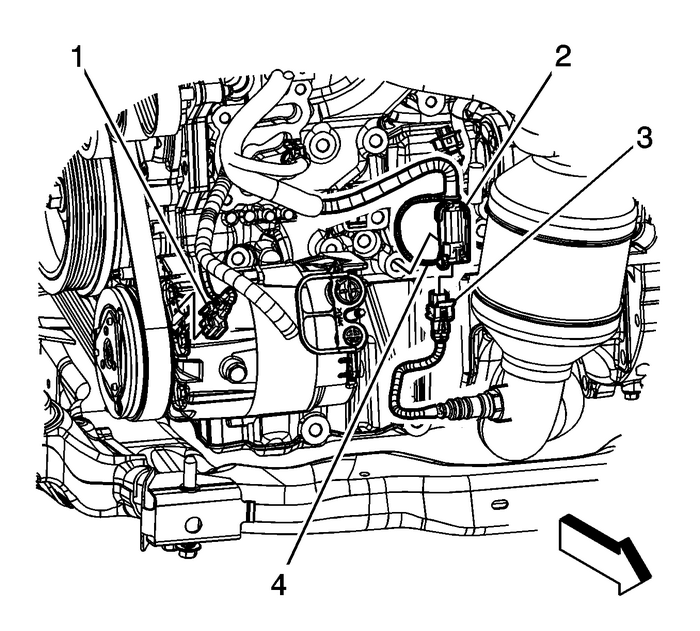
Disconnect the A/C compressor-(1).Disconnect the radiator outlet hose from the engine. Refer toRadiator Outlet Hose Replacement.Disconnect the radiator inlet hose from the engine. Refer toRadiator Inlet Hose Replacement.
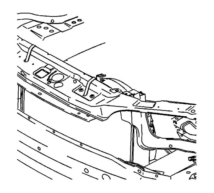
Secure the cooling module to the upper body structureRemove the engine control module (ECM). Refer toEngine Control Module Replacement.Support the engine in the cradle with wood blocks.Remove right side engine mount. Refer toEngine Mount Replacement - Right Side.Disconnect the A/C high pressure switch harness.Discharge A/C system. Refer toRefrigerant Recovery and Recharging.Disconnect the electrical connector from the air conditioningrefrigerant pressure sensor valve.
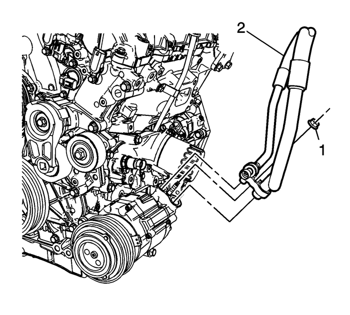
Remove the compressor hose nut (1) at the compressorRemove the compressor hose (2) from the compressor.Remove the A/C compressor hose from the compressor, thenreposition the hose out of the way.Disconnect the Coolant Recovery Reservoir Vent Hose. Refer toCoolant Recovery Reservoir Vent Hose Replacement.Disconnect the Coolant Recovery Reservoir Outlet Hose. RefertoCoolant Recovery Reservoir Outlet Hose Replacement.Disconnect the heater inlet hose from the engine.Disconnect the heater outlet hose from the engine.
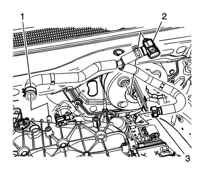
Release the spring clamp (1) and remove the power brakebooster vacuum hose from the intake manifold vacuum port.Remove the power brake booster vacuum sensor (2) from thepower vacuum brake booster.Disconnect the fuel feed line. Refer toFuel Feed Pipe Replacement.Disconnect the fuel EVAP emission line. Refer toPlastic Collar Quick Connect Fitting Service.Disconnect the coolant reservoir hose from the engine toreservoir.Raise and support the vehicle. Refer toLifting and Jacking the Vehicle.Remove the lower transaxle-to-engine bolts.Remove the torque converter inspection cover.Remove the starter. Refer toStarter Replacement.Mark the relationship of the flywheel to the torque converterfor reassembly.Remove the torque converter to flywheel bolts.
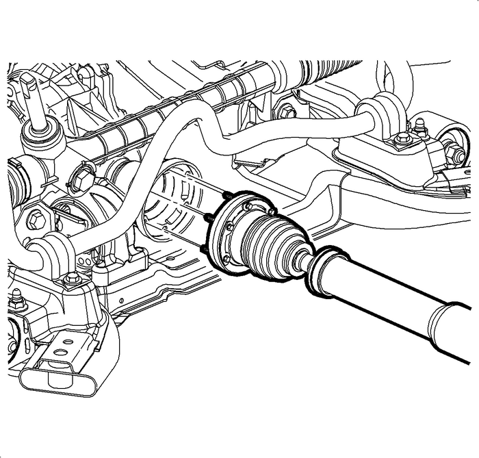
For AWD, remove the propeller shaft completely from thevehicle. Refer toPropeller Shaft Replacement.For AWD, remove the transfer case. Refer toTransfer Case Assembly Replacement.Remove the front wheels. Refer toTire and Wheel Removal and Installation.Remove the right and left engine splash shields.Disconnect the transmission cooler lines from theradiator.Disconnect the power steering hoses from the power steeringcooler.Remove the left and right tie rod ends from the steeringknuckles. Refer toSteering Linkage Outer Tie Rod Replacement.Remove the left and right stabilizer bar links. Refer toStabilizer Shaft Link Replacement.Disconnect the left and right lower ball joints. Refer toLower Control Arm Replacement.Disconnect the left and right axle shafts from the hubs.Refer toFront Wheel Drive Shaft Replacement.
Note:In order to prevent possible SIR system deployment, do notattempt to rotate the steering shaft.
Disconnect the steering shaft coupling from the steeringgear. Refer toIntermediate Steering Shaft Replacement.Remove the front exhaust pipe. Refer toCatalytic Converter Replacement - Left SideandCatalytic Converter Replacement - Right Side.Support the engine in the cradle with wood blocks.Remove the left engine mount. Refer toTransmission Mount Replacement - Left Side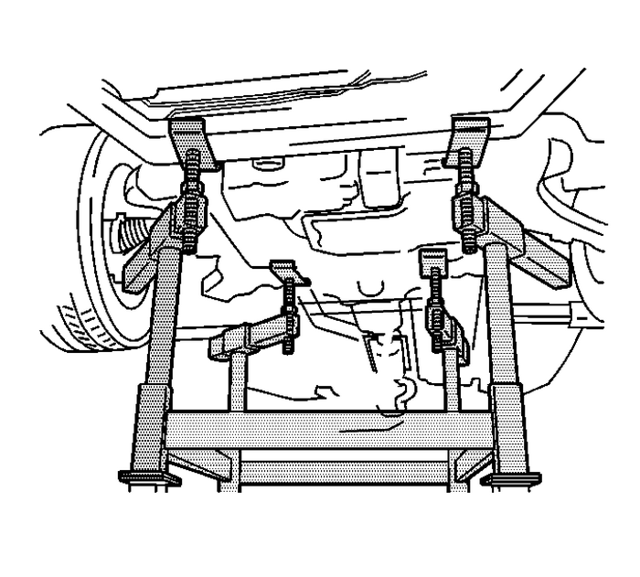
Position the engine support table under the powertrainassembly.With the table positioned, fully raise the table to contactwith the powertrain assembly.Remove the front crossmember support bracket to bodybolts.Remove the cradle bolts.
Note:During the powertrain removal, support the vehicle body byplacing a jack at the rear of the vehicle.
Slowly raise the vehicle until the powertrain assembly isclear of the vehicle.Remove the front transmission mount from the frame. Refer toTransmission Front Mount Replacement.Separate the engine from the transmission.Transfer parts as needed.Installation ProcedureAlign the engine to the transmission.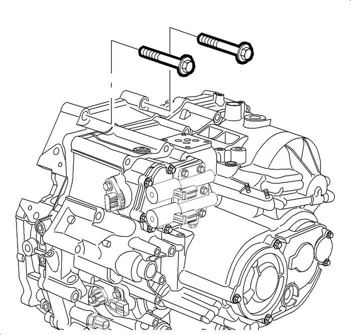
Caution:Refer toFastener Caution.
Install the transmission-to-engine mounting bolts. Tightenthe bolts to50-Y(37-lb-ft).Install the right engine mount. Refer toEngine Mount Replacement - Right Side.Install the front transmission mount to the engine. Refer toTransmission Front Mount Replacement.Install the powertrain assembly to the vehicle.Install the cradle bolts. Refer toDrivetrain and Front Suspension Frame Replacement.Install the front crossmember support bracket to body bolts.Tighten the bolts to50-Y(37-lb-ft)Remove the engine support table.Install the front transmission mount bolts to the body. RefertoTransmission Front Mount Replacement.Remove the wood blocks from the cradle.Install the lower transaxle-to-engine bolts and tighten to50-Y(37-lb-ft).For AWD, install the transfer case. Refer toTransfer Case Assembly Replacement.Install the torque converter-to-flywheel bolts and tighten to60-Y(44-lb-ft).Install the starter. Refer toStarter Replacement.Install the torque converter inspection cover.Install the torque converter inspection cover and tighten thebolts to12-Y(106-lb-in).Install the front exhaust pipe. Refer toCatalytic Converter Replacement - Left SideandCatalytic Converter Replacement - Right Side.Connect the steering shaft coupling from the steering gear.Refer toIntermediate Steering Shaft Replacement.For AWD, install the propeller shaft. Refer toPropeller Shaft Replacement.Install the left and right axle shaft nuts. Refer toFront Wheel Drive Shaft Replacement.Connect the left and right lower ball joints. Refer toLower Control Arm Replacement.Install the left and right stabilizer bar links. Refer toStabilizer Shaft Link Replacement.Install the left and right tie rod ends to the steeringknuckles. Refer toSteering Linkage Outer Tie Rod Replacement.Connect the transmission cooler lines to thetransmission.Install the A/C compressor. Refer toAir Conditioning Compressor Replacement.Install the right and left engine splash shields.Connect the transmission cooler lines to the radiator.Connect the power steering hoses to the power steeringcooler.Install the front tires. Refer toTire and Wheel Removal and Installation.Lower the vehicle.Connect the range selector cable-(2) to the rangeselector cable bracket.Connect the wiring harness to the underhood junction block.refer toAccessory Wiring Junction Block Replacement.Connect right side inline electrical connector.Install the fuel EVAP line.Connect the fuel feed line. Refer toFuel Feed Pipe Replacement.Connect the heater inlet hose to the engine.Connect the heater outlet hose to the engine.Install the A/C compressor hose to the compressor.Connect the transmission cooler lines to the radiator.Connect the power steering hoses to the power steeringcooler.Connect the Coolant Recovery Reservoir Vent Hose. Refer toCoolant Recovery Reservoir Vent Hose Replacement.Connect the Coolant Recovery Reservoir Outlet Hose. Refer toCoolant Recovery Reservoir Outlet Hose Replacement.
Install the power brake booster vacuum sensor (2) to thepower vacuum brake booster.Install the starter positive cable and tighten to10-Y(89-lb-in).Connect the coolant reservoir hose from the engine toreservoir.Connect the A/C high pressure switch harness.Connect the electrical connector to the air conditioningrefrigerant pressure sensor valve.Connect the generator positive cable and nut and tighten to12-Y(106-lb-in).Install the ECM. Refer toEngine Control Module Replacement.Connect the radiator outlet hose to the engine. Refer toRadiator Outlet Hose Replacement.Connect the radiator inlet hose to the engine. Refer toRadiator Inlet Hose Replacement.Fill the vehicle with coolant. Refer toCooling System Draining and Filling.Fill the vehicle with engine oil. Refer toEngine Oil and Oil Filter Replacement.Connect the wiring harness to the underhood junctionblock.Connect the transmission shifter cable.Remove the cooling module support.Install the battery tray and battery. Refer toBattery Tray Replacement.Install battery hold down retainer bracket.Install the air cleaner assembly. Refer toAir Cleaner Assembly Replacement.Install the intake manifold cover. Refer toIntake Manifold Cover Replacement.Connect the negative battery cable. Refer toBattery Negative Cable Disconnection and Connection.Perform the throttle learn procedure. Refer toQ38 Throttle Body: Throttle/Idle Learn.
 Engine Support Fixture Engine Block Engine Mounts
Special ToolsJ 28467-B Universal Engine Support FixtureJ 28467-7A Bolt HookJ-28467-13 Engine Support Fixture AdaptersJ 28467-34 Lift Hook Wing Nut and WasherJ 36462-A Engine Support Adapter Leg SetJ 4 ...
 Radiator Outlet Hose Replacement (LEA) Engine Cooling Radiator
Special ToolsJ 38185Hose Clamp PliersRemoval ProcedureDrain the cooling system. Refer toCooling System Draining and Filling.Raise and support the vehicle. Refer toLifting and Jacking the Vehicle.Disen ...
Other materials:
Timing Chain Idler Sprocket Installation - Left Side Valvetrain Valvetrain Timing Timing Belt/Chain
Ensure that the left camshaft intermediate drive chainidler-(2) is being installed. The recessedhub-(3) and the larger sprocket of the left camshaftintermediate drive chain idler is installed outward. The raised huband the smaller sprocket of the left camshaft intermediate drivechain idler is instal ...
