Chevrolet Equinox Service Manual: Drive Range, Third Gear (Gen 2/Hybrid) Automatic Transmission Unit
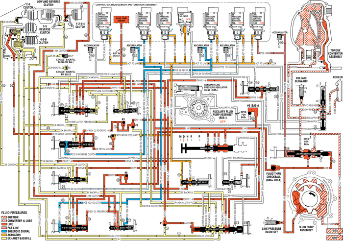
As vehicle speed increases and operating conditions becomeappropriate, the transmission control module (TCM) processes inputsignals from the automatic transmission input and output speedsensors, the throttle position sensor and other vehicle sensors todetermine the precise moment to command OFF the normally-low 26pressure control solenoid. At the same time the 35R pressurecontrol solenoid is also commanded ON to regulate 3-5 clutch apply,and the transmission shifts into Third gear. The manual valveremains in the Drive (D) position and line pressure continues tofeed the drive fluid circuit.
3-5-Reverse Clutch Applies35R Pressure Control (PC) Solenoid
The 35R PC solenoid is commanded ON, allowing actuator feedlimit fluid to enter the PCS 35 reverse clutch fluid circuit. PCS35 reverse clutch fluid is routed through orifice #26 to the3-5-reverse clutch regulator valve.
3-5-Reverse Clutch Regulator Valve
PCS 35 reverse clutch fluid, at the 3-5-reverse clutchregulator valve, opposes 3-5-reverse clutch regulator valve springforce and 35 reverse clutch feedback fluid pressure to regulate 35reverse clutch feed/drive 1-6 pressure into the 35 reverse clutchcircuit. The 35 reverse clutch fluid is then routed through orifice#25 to the 3-5-reverse clutch assembly, through orifice #6 to thespring end of the 3-5-reverse clutch regulator valve and throughorifice #33 to the #4 ball check valve.
3-5-Reverse Clutch
35 reverse clutch fluid enters the 3-5-reverse and 4-5-6clutch housing assembly to move the 3-5-reverse clutch pistonagainst spring force and exhaust backfill fluid pressure to applythe 3-5-reverse clutch plates.
#4 Ball Check Valve
35 reverse clutch feed fluid unseats the #4 ball check valve,allowing excess pressure to pass into the actuator feed limitcircuit. This helps to control clutch apply fluid pressure andclutch apply feel.
Accumulator
PCS 35 reverse clutch fluid is also routed to an accumulatorvalve. The accumulator valve is used to dampen any pressureirregularities occurring in the PCS 35 reverse clutch fluidcircuit. This helps to control clutch apply fluid pressure andclutch apply feel.
2-6 Clutch Releases26 Pressure Control (PC) Solenoid
The 26 PC solenoid is commanded OFF, allowing PCS 26 clutchfluid to exhaust from the 2-6 clutch regulator valve.
2-6 Clutch Regulator Valve
2-6 clutch regulator valve spring force moves the valve tothe released position, allowing 26 clutch fluid from the 2-6 clutchto pass through the valve and enter the exhaust backfill fluidcircuit.
2-6 Clutch
2-6 clutch spring force moves the 2-6 clutch piston torelease the 2-6 clutch plates and force 26 clutch fluid to exhaustfrom the transmission case assembly. The exhausting 26 clutch fluidpressure is routed to the 2-6 clutch regulator valve where itenters the exhaust backfill fluid circuit.
Drive Range, ThirdGear-–-Gen 2/Hybrid
 Drive Range, First Gear Automatic Transmission Unit
As the vehicle speed increases, the transmission control module-(TCM) receives inputsignals from the automatic transmission input and output speed sensors, throttle positionsensor and other vehicle se ...
 Drive Range, Sixth Gear (Gen 2/Hybrid) Automatic Transmission Unit
As vehicle speed increases, the transmission control module(TCM) processes input signals from the automatic transmission inputand output speed sensors, the throttle position sensor and othervehicle se ...
Other materials:
Front Floor Console Flood Lamp Replacement Consoles Center Console
Front Floor Console Flood Lamp ReplacementCalloutComponent NamePreliminary ProcedureRemove the roof console. Refer toRoof Console Replacement.1Front Floor Console Flood LampProcedureDisconnect electrical connector. ...
