Chevrolet Equinox Service Manual: Crankshaft and Bearing Installation Engine Block Cylinder Block Crankshaft
Special ToolsEN-8087Cylinder Bore Checking GaugeEN 45059Angle Meter
For equivalent regional tools, refer toSpecial Tools.

Note:
Crankshaft bearings MUST be separated, marked, or organizedin a way to ensure installation to their original location andposition, when suitable for use.If crankshaft bearing failure is due to other than normalwear, investigate the cause. Inspect the crankshaft or connectingrod bearing bores.Inspect the connecting rod bearing bores or crankshaft mainbearing bores using the following procedure:
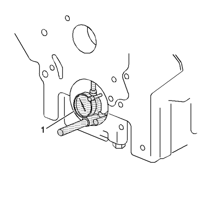
Tighten the bedplate to specification using theEN 45059meter.Measure the bearing bore for taper andout-of-round using theEN-8087gauge-(1).No taper or out-of-round shouldexist.Bearing SelectionMeasure the bearing clearance to determine the correctreplacement bearing insert size. There are 2-methods tomeasure bearing clearance. Method-A gives more reliableresults and is preferred.Method-A yields measurement from which the bearingclearance can be computed.Method-B yields the bearing clearance directly.Method-B does not give any indication of bearingrun-out.
Note:Do not mix inserts of different nominal size in the samebearing bore.
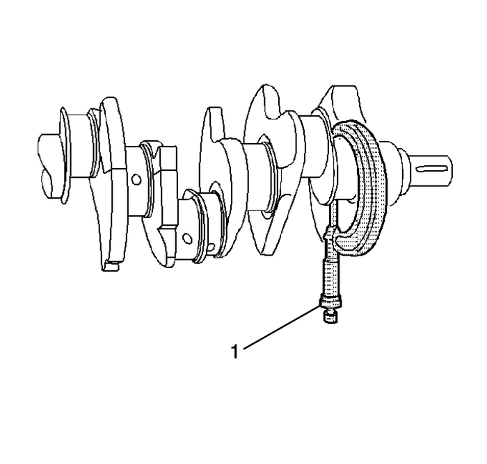
To measure bearing clearance using Method-A, usethe following procedure:Measure the crankshaft bearing journal diameter with amicrometer-(1) in several places, 90-degreesapart. Average the measurements.Measure the crankshaft bearing journal taper andrunout.Install the lower crankcase and tighten the bearing cap boltsto specification.Measure bearing inside diameter-(ID) in severalplaces 90-degrees apart, average measurements.Subtract journal measurement from bearing ID measurement todetermine clearance.Determine whether clearance is within specification.If out of specification, choose different inserts.Measure the connecting rod inside diameter in the samedirection as the length of the rod with an insidemicrometer.Measure the crankshaft main bearing inside diameter with aninside micrometer.
To measure bearing clearance using Method-B, usethe following procedure:Clean the used bearing inserts.Install the used bearing inserts.Place a piece of gaging plastic across the entire bearingwidth.Install the bearing caps.
Caution:In order to prevent the possibility of cylinder block orcrankshaft bearing cap damage, the crankshaft bearing caps aretapped into the cylinder block cavity using a brass, lead, or aleather mallet before the attaching bolts are installed. Do not useattaching bolts to pull the crankshaft bearing caps into the seats.Failure to use this process may damage a cylinder block or abearing cap.
Install the bearing cap bolts to specification.Note:Do not rotate the crankshaft.
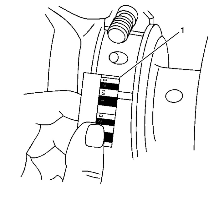
Remove the bearing cap, leaving the gauging plastic in place.It does not matter whether the gauging plastic adheres to thejournal or to the bearing cap.Measure the gauging plastic at its widest point with thescale-(1) printed on the gauging plastic package.Remove the gauging plastic. Cylinder Head Assemble Engine Block Cylinder Head
Special ToolsEN 8062 Valve Spring Compressor – Head OffEN 46116 Valve Stem Seal Remover/InstallerEN 46117 Valve Stem Key Remover/InstallerEN 46119 Off-Vehicle Valve Spring Compressor AdapterEN 46122 ...
 Engine Block Cleaning and Inspection Engine Block
Special ToolsEN 8087Cylinder Bore GaugeEN 28410Gasket RemoverFor equivalent regional tools, refer toSpecial Tools.Cleaning ProcedureRemove any old thread sealant, gasket material or sealantusingEN 284 ...
Other materials:
Exhaust Manifold Installation (LAF, LEA, or LUK) Exhaust Exhaust Manifold
Caution:Refer toFastener Caution.Install new exhaust manifold studs and tighten to 10-Y (89-lb-in).Install the secondary air injection pipe assembly-(1).Install the secondary air injection pipe assembly bolts-(2) and tighten to 10-Y-(89-lb-in).Install the exhaust manifold gasket-(3).Install the exh ...
