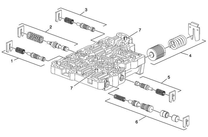
Chevrolet Equinox Service Manual: Control Valve Lower Body Assembly Cleaning and Inspection Automatic Transmission Unit

Warning:Valve springs can be tightly compressed. Use care whenremoving retainers and plugs. Personal injury could result. Caution:After cleaning the transmission components, allow to air dry.Do not use cloth or paper towels in order to dry any transmissioncomponents. Lint from the towels can cause componentfailure. Caution:Do not reuse cleaning solvents. Previously used solvents maydeposit sediment which may damage the component. Preliminary Procedure Clean and inspect all valve components and the valve body. The control valve lowerbody is replaceable only as an assembly. | |
1 | 3–5 Reverse Clutch Boost Valve Train |
2 | Accumulator Feed Limit Valve Train |
3 | 4–5–6 Clutch Boost Valve Train |
4 | 4–5–6 Clutch Accumulator Piston Assembly |
5 | 1–2–3–4 Clutch Boost Valve Train |
6 | 1–2–3–4 Clutch Regulator Valve Train |
7 | Control Valve Body Locating Pins (Qty: 2) Note:Inspect Valve Body locating pins for proper installed height of 4.25-mm (0.17-in). |
 Control Valve Lower Body Automatic Transmission Unit
Control Valve Lower Body(2)Line(11)Actuator Feed Limit(14)PCS R1/456 Clutch(19)R1/456 Clutch Feed(20)R1 Feedback(21)R1 Supply(23)PCS 35 Reverse Clutch(28)35 Reverse Clutch(29)35 Reverse Clutch Feedbac ...
 Control Valve Lower Body Spacer Plate Assembly Automatic Transmission Unit
Control Valve Lower Body Spacer Plate Assembly222343.(5350019512353o2o29029213650360(2)Line(3)Decrease(5)TCC Release(6)TCC Apply(10)Compensator Feed(11)Actuator Feed Limit(14)PCS R1/456 Clutch(19)R1/4 ...
Other materials:
Cooling Fan Description and Operation (LEA) Engine Cooling Radiator Fan
System OverviewThe engine cooling fan system is composed of one cooling fan, 2-relays, the enginecontrol module (ECM), and the associated wiring. The cooling fan assembly includes1-resistor mounted in the cooling fan shroud. The cooling fan resistor may be a standalone component, or a part of the co ...
