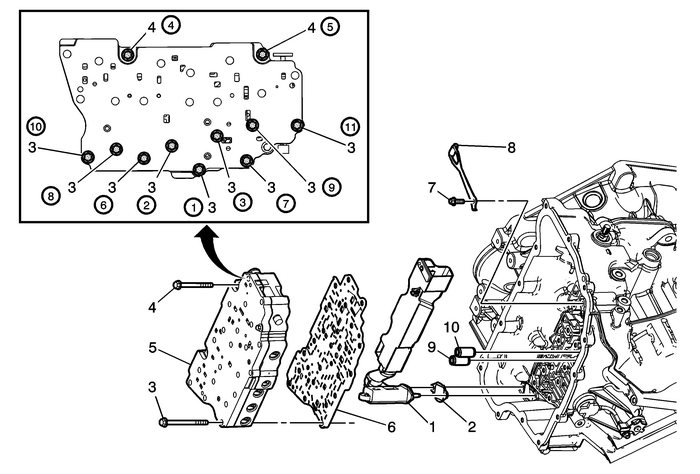
Chevrolet Equinox Service Manual: Control Valve Body Replacement Automatic Transmission Unit Control Valve Body

Preliminary Procedure Remove the control solenoid valve and transmission control module assembly. RefertoControl Solenoid Valve and Transmission Control Module Assembly Replacement. | |
1 | Fluid Level Control Valve |
2 | Fluid Level Control Valve Gasket |
3 | Control Valve Body Bolt M6 x 60 (Qty:-9) Caution:Refer toFastener Caution. Procedure Tighten in specified sequence. Tighten11-Y (97-lb-in) |
4 | Control Valve Body Bolt M6 x 53 (Qty:-2) Procedure Tighten in specified sequence. Tighten11-Y (97-lb-in) |
5 | Control Valve Body Assembly |
6 | Control Valve Body Spacer Plate Assembly |
7 | Manual Shaft Detent Spring Bolt M6 x 16 (Qty: 1) Procedure Tighten in specified sequence. Tighten12-Y (106-lb-in) |
8 | Manual Shaft Detent Lever Spring Assembly |
9 | 1-2-3-4 Clutch Fluid Passage Seal Procedure Discard the seal. It is not reusable. |
10 | Low/Reverse Clutch Fluid Passage Seal Procedure Discard the seal. It is not reusable. |
 Control Valve Body Cover Installation Automatic Transmission Unit Control Valve Body
Control Valve Body Cover InstallationCalloutComponent Name1Input Speed Sensor Connector2Output Speed Sensor Connector3Shift Position Switch Connector4Control Valve Body Cover Wiring Connector Hole Sea ...
 Control Valve Body Spacer Plate Assembly - Case Side Automatic Transmission Unit
Control Valve Body Spacer PlateAssembly-–-Case Side(2)Line(7)Cooler Feed(9)Regulated Apply(10)Exhaust Backfill(12)PCS Line(16)R1/456 Clutch Feedback(17)R1(19)Reverse(20)35 Reverse Clutch Feed(21)35 ...
Other materials:
Engine Flywheel Replacement Flywheel/Flexplate
Engine Flywheel ReplacementCalloutComponent NamePreliminary ProcedureRemove the transmission. Refer toTransmission Replacement.Special ToolsEN-43653Engine Flywheel Holding Tool.For equivalent regional tools, refer toSpecial Tools.1Engine Flywheel Fastener (Qty:-6)Caution:Refer toFastener Caution.Not ...
