Chevrolet Equinox Service Manual: Camshaft Cover Replacement - Left Side Valvetrain Camshaft
Special Tools
EN-46101Spark Plug Tube Seal Guide
For equivalent regional tools, refer toSpecial Tools.
Removal ProcedureRemove the ignition coils. Refer toIgnition Coil Replacement - Bank 2.Disconnect and remove the engine harness from the camshaftcover.Remove the intake manifold. Refer toIntake Manifold Replacement.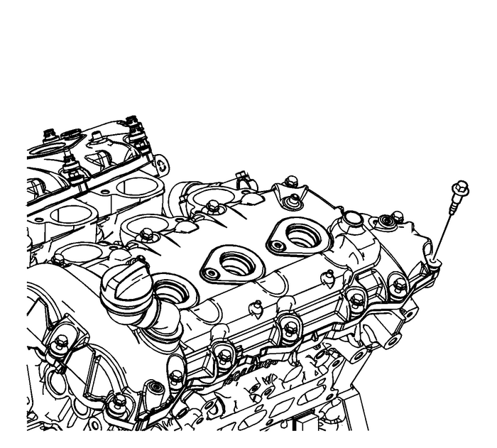
Remove the left camshaft cover bolts.Remove the left camshaft cover from the left cylinderhead.Clean the mating surfaces of the cylinder head and thecamshaft cover. Refer toCamshaft Cover Cleaning and Inspection
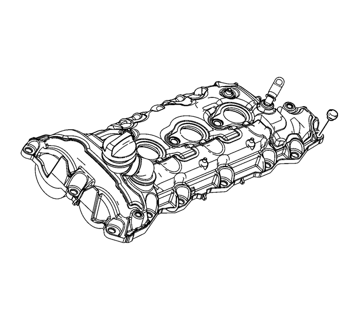
Install theEN-46101guideonto the spark plug tubes of the left cylinderhead.Installation Procedure
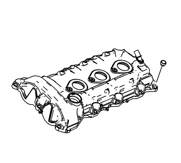
Install new camshaft cover bolt grommets prior to installingthe camshaft cover bolts.
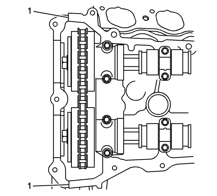
Place a bead 8-mm (0.3150-in) indiameter by 4-mm (0.1575-in) in height of RTVsealant equivalent, on the engine front cover splitlines-(1).
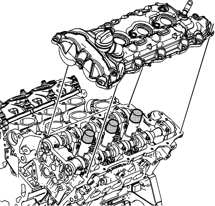
Place the left camshaft cover into position onto the leftcylinder head.
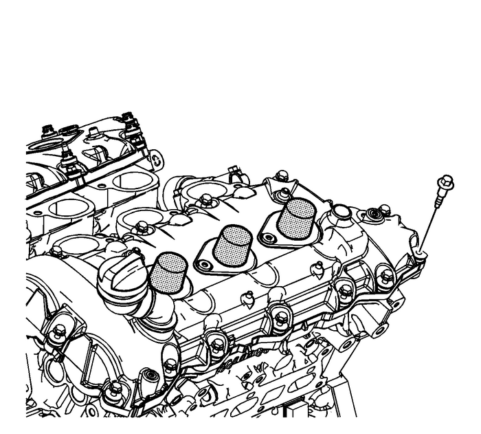
Caution:Refer toFastener Caution.
Loosely install the left camshaft cover bolts.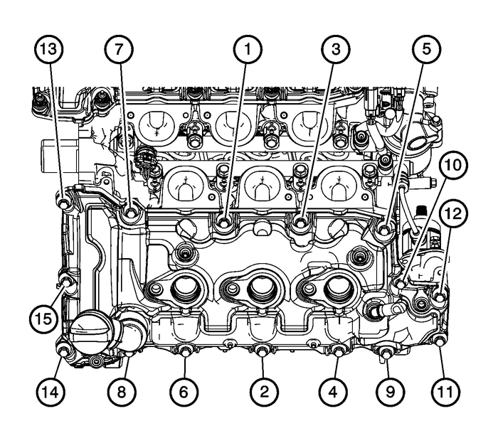
Tighten the left camshaft cover bolts in the sequence shownto10-Y(89-lb-in).Connect and install the engine harness to the camshaftcover.Install the intake manifold. Refer toIntake Manifold Replacement.
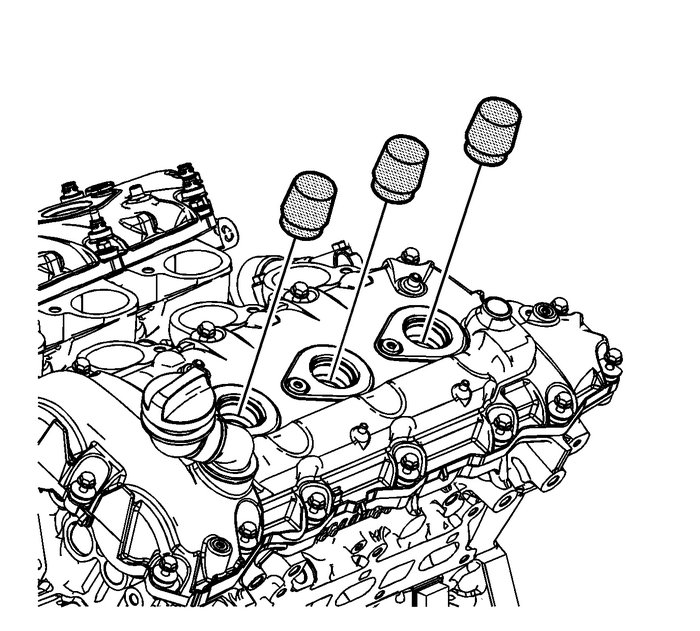
Remove theEN-46101guidefrom the spark plug tubes of the left cylinderhead.Install the ignition coils. Refer toIgnition Coil Replacement - Bank 2.
 Camshaft Cover Replacement - Right Side Valvetrain Camshaft
Special ToolsEN-46101Spark Plug Tube Seal GuideFor equivalent regional tools, refer toSpecial ToolsRemoval ProcedureRemove the ignition coils. Refer toIgnition Coil Replacement - Bank 1Disconnect and ...
 Water Pump Replacement (LFX) Engine Cooling Coolant Pump
Special Tools EN 46104 Water Pump Pulley HolderFor equivalent regional tools refer toSpecial ToolsRemoval ProcedureDrain the cooling system. Refer toCooling System Draining and Filling.Remove the gene ...
Other materials:
Keys
Warning
Leaving children in a vehicle with
a Remote Keyless Entry (RKE)
transmitter is dangerous and
children or others could be
seriously injured or killed. They
could operate the power windows
or other controls or make the
vehicle move. The windows will
function w ...
