Chevrolet Equinox Service Manual: Brake Pedal Assembly Replacement Hydraulic Brakes Brake Pedal Assembly
Removal ProcedureRemove the instrument carrier. Refer toInstrument Carrier Replacement.Remove the accelerator pedal position sensor. Refer toAccelerator Pedal with Position Sensor Assembly ReplacementorAccelerator Pedal with Position Sensor Assembly Replacement.Remove the brake pedal position sensor. Refer toBrake Pedal Position Sensor Replacement.

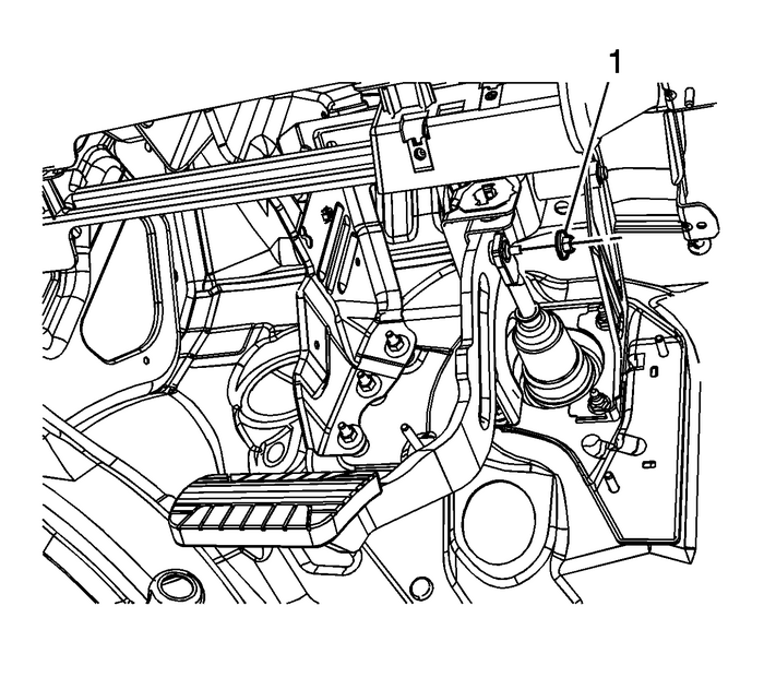
Remove the brake booster pushrod nut-(1).Disconnect the brake booster pushrod from the brake pedalpivot pin.

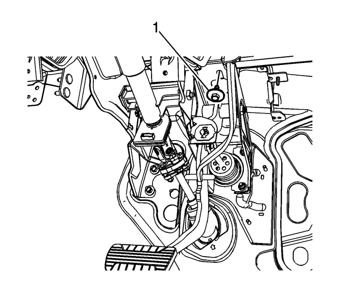
Remove the brake pedal bracket bolt-(1).

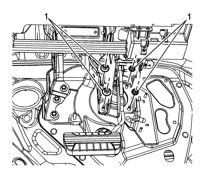
Remove the brake pedal bracketnuts-(1)-and the brake pedal assembly.Installation Procedure

Install the brake pedal assembly to the dash panelreinforcement plate.
Caution:Refer toFastener Caution.
Install the brake pedal bracketnuts-(1)-and tighten to-25-Y(18-lb-ft).
Install the brake pedal bracketbolt-(1)-and tighten to-25-Y(18-lb-ft).

Connect the brake booster pushrod from the brake pedal pivotpin.Install the brake booster pushrodnut-(1)-and tighten to-25-Y(18-lb-ft).Install the brake pedal position sensor. Refer toBrake Pedal Position Sensor Replacement.Install the accelerator pedal position sensor. Refer toAccelerator Pedal with Position Sensor Assembly ReplacementorAccelerator Pedal with Position Sensor Assembly Replacement.Install the instrument carrier. Refer toInstrument Carrier Replacement.
 Brake Fluid Level Indicator Switch Replacement
Removal ProcedureRemove the accessory wiring junction block. Refer toAccessory Wiring Junction Block Replacement.Disconnect the brake fluid level indicator switch electricalconnector.While compressing ...
 Rear Disc Brake Pads Replacement Disc Brakes Brake Pads
Removal ProcedureWarning:Refer toBrake Dust Warning.Inspect the fluid level in the brake master cylinder reservoir.If the brake fluid level is midway between the maximum-full point and the minimumallo ...
Other materials:
Input Shaft Seal Replacement - Left (RPO MHC) Automatic Transmission Unit
Input Shaft Seal Replacement - LeftCalloutComponent Name1Transfer Case Input Shaft Seal – LeftCaution:Do not use a screwdriver or punch to remove or install theseal. Using a screwdriver or punch to remove or install the sealmay damage the aluminum housing sealing surface.ProcedureLightly lubricate ...
