
Chevrolet Equinox Service Manual: Secondary Camshaft Intermediate Drive Chain Installation - Left Side Valvetrain Camshaft
Special ToolsEN 48383Camshaft Retaining ToolsEN 48589Crankshaft Rotation Socket
For equivalent regional tools, refer toSpecial Tools.
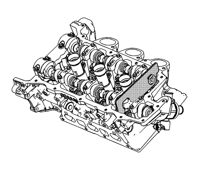
Note:There should be no need to rotate the camshaft more than10-degrees. Using the hex cast into the camshaft rotatethe camshaft in order to install theEN 48383tools.
Install the EN-48383-1 onto the rear ofthe left camshafts.Note:All camshafts must be locked in place before installation ofany camshaft drive chains.
Ensure that the EN-48383-1 is fullyseated onto the camshafts.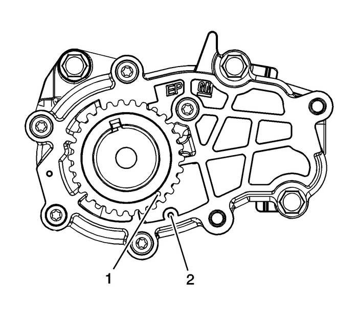
Ensure the crankshaft is in the stage one timing positionwith the crankshaft sprocket timing mark-(1) aligned tothe stage one timing mark on the oil pump cover-(2)using theEN 48589socket. Refer toTiming Chain Alignment Diagram.
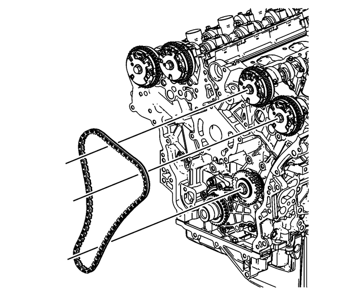
Install the left secondary camshaft drive chain.
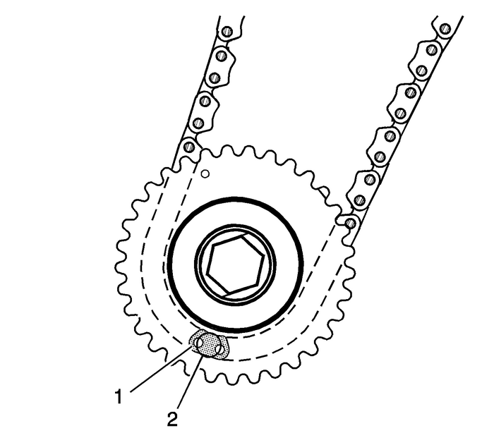
Place the left secondary camshaft drive chain around theinner sprocket of the left camshaft intermediate drive chain idlerwith the timing camshaft drive chain link-(1) aligned tothe alignment access hole-(2) made in the left camshaftintermediate drive chain idler outer sprocket.
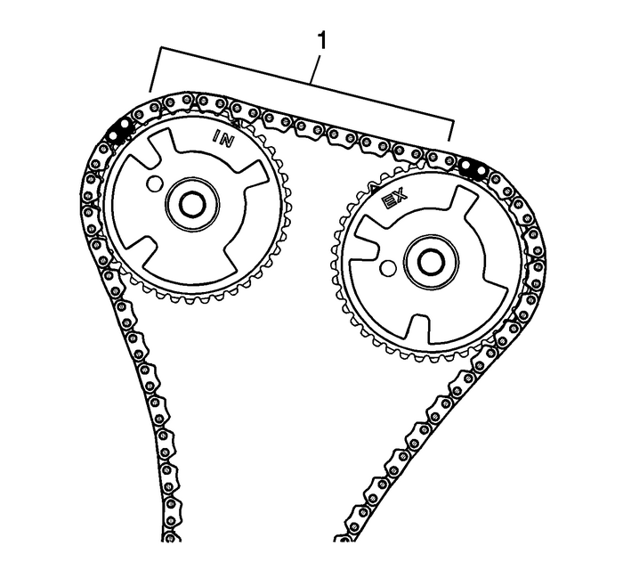
Wrap the secondary camshaft drive chain around both leftactuator drive sprockets.Ensure there are 10-links-(1) betweenthe timing camshaft drive chain links for the camshaft positionactuator sprockets.
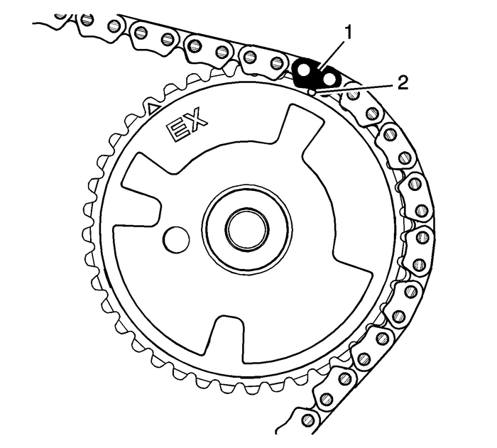
Align the left exhaust camshaft position actuator sprocketalignment circle mark-(2) with the timing camshaft drivechain link-(1).
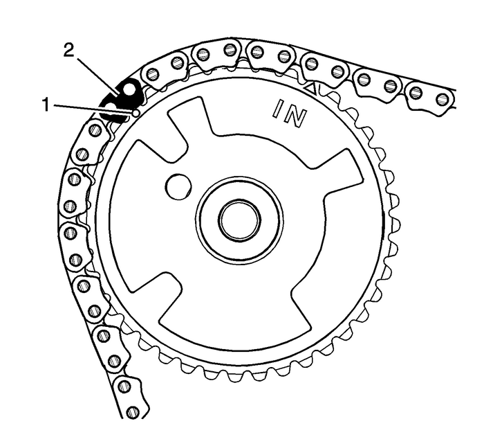
Align the left intake camshaft position actuator sprocketalignment circle mark-(1) with the timing camshaft drivechain link-(2).
 Camshaft Position Actuator Replacement - Bank 2 Valvetrain Camshaft
Special Tools EN-48313 Timing Chain Retention ToolFor equivalent regional tools, refer toSpecial Tools.Removal ProcedureRemove the left camshaft cover. Refer toCamshaft Cover Replacement - Left Side.R ...
 Crankshaft Balancer Installation Engine Block Cylinder Block Crankshaft
Special ToolsEN-48585 Crankshaft Balancer GuideEN-48953 Camshaft Actuator Locking ToolEN 38122-A Crankshaft Balancer HolderEN 43653 Flywheel Holding ToolEN 45059 Angle MeterFor equivalent regional too ...
Other materials:
Input and Output Speed Sensor Removal Automatic Transmission Unit
Input and Output Speed Sensor RemovalCalloutComponent Name1A/Trans Output Speed Sensor Bolt-M6-x-18-(Qty:-1)2A/Trans Output Speed Sensor Assembly3Input Speed Sensor Bolt M6-x-23-(Qty:-1)4Input Speed Sensor AssemblyNote:Compress the locking tabs on the plug to release it from the case and to avoid da ...
