Chevrolet Equinox Service Manual: Reverse (Gen 2/Hybrid) Automatic Transmission Unit
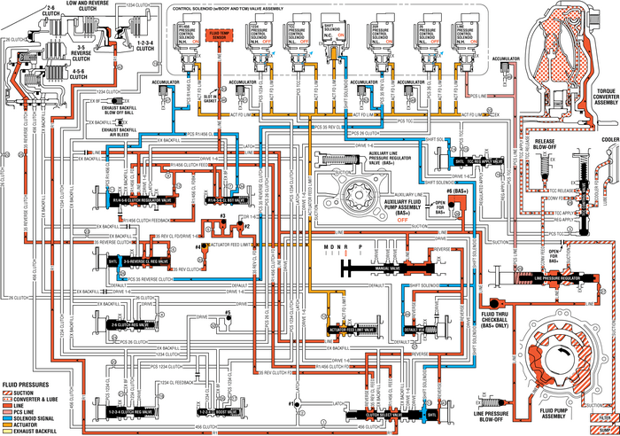
When the gear selector lever is moved to the Reverse (R)position (from the Park position) the normally-low 35R pressurecontrol solenoid is commanded ON and the following changes occur inthe transmission’s hydraulic and electricalsystems:
3-5-Reverse Clutch AppliesManual Valve
With the manual valve in the reverse position, line pressureis directed into the reverse fluid circuit. Reverse fluid is thenrouted to the clutch select valve and to the default overridevalve.
Clutch Select Valve
Reverse fluid is routed to a differential area of the clutchselect shuttle valve and assists shift solenoid fluid, present atthe valve from Park position, in holding the clutch select valveagainst clutch select valve spring force. Reverse fluid passesthrough the clutch select valve into the 35 reverse clutch feedcircuit and is routed to the #2 ball check valve. R1/456 clutchfeed fluid, present at the valve from Park position, continues topass through the valve into the R1 circuit in order to keep the lowand reverse clutch applied.
#2 Ball Check Valve
3-5 reverse fluid seats the #2 ball check valve against thedrive 1-6 fluid passage, and enters the 35 reverse/drive 1-6circuit. 35 reverse/drive 1-6 fluid is routed to the #3 ball checkvalve.
#3 Ball Check Valve
35 reverse/drive 1-6 fluid unseats the #3 ball check valveand is routed to the 3-5-reverse clutch regulator valve.
35R Pressure Control (PC) Solenoid
The 35R PC solenoid is energized (ON), allowing actuator feedlimit fluid to enter the PCS 35 reverse clutch fluid circuit. PCS35 reverse clutch fluid is then routed through orifice #26 to the3-5-reverse clutch regulator valve.
3-5-Reverse Clutch Regulator Valve
PCS 35 reverse clutch fluid, at the 3-5-reverse clutchregulator valve, opposes 3-5-reverse clutch regulator valve springforce and orificed 35 reverse clutch feedback fluid pressure toregulate 35 reverse clutch feed/drive 1-6 pressure into the 35reverse clutch circuit. 35 reverse clutch fluid is then routedthrough orifice #25 to the 3-5-reverse clutch, and through orifice#33 to the #4 ball check valve.
3-5-Reverse Clutch
35 reverse clutch fluid enters the 3-5-reverse and 4-5-6clutch housing assembly to move the 3-5-reverse clutch pistonagainst spring force to apply the 3-5-reverse clutch plates.
#4 Ball Check Valve
35 reverse clutch feed fluid unseats the #4 ball check valve,allowing excess pressure to pass into the actuator feed limitcircuit. This helps to control clutch apply fluid pressure andclutch apply feel.
Accumulator
PCS 35 reverse clutch fluid is also routed to an accumulatorvalve. The accumulator valve is used to dampen any pressureirregularities occurring in the PCS 35 reverse clutch fluidcircuit. This helps to control clutch apply fluid pressure andclutch apply feel.
Fluid Pressure Directed in Preparation for a PossibleDefault ActionReverse fluid is directed to the default override valve inpreparation for Reverse (R) range operation in the event of atransmission default action. If a transmission electrical componentmalfunction occurs, all solenoids will default to their normalstate. The shift solenoid will default to its normally-closed state(OFF), and shift solenoid fluid will exhaust, allowing defaultoverride valve spring force to move the default override valve tothe released position. With the default override valve in thereleased position, reverse fluid pressure passes through the valveinto the default circuit and is routed to the 3-5-reverse clutchregulator shuttle valve. Default fluid pressure replaces exhaustingPCS 35 reverse clutch fluid pressure to keep the 3-5-reverse clutchregulator valve in the applied position, and allow continuedReverse (R) range operation. Refer to Drive Range– FourthGear Default for a complete description of the default actions thatoccur during an electrical component malfunction.
Reverse-–-Gen2/Hybrid
 Reverse Automatic Transmission Unit
When the gear selector lever is moved to the Reverse (R) position (from the Park position)the normally high 35R pressure control solenoid 2 is commanded ON and the followingchanges occur in the transm ...
 Ignition Transmission Lock Check Automatic Transmission Unit
While parked and with the parking brake set, try to turn the ignition to LOCK/OFFin each shift lever position.The ignition should turn to LOCK/OFF only when the shift lever is in P-(Park).The ignition ...
Other materials:
Fastener Caution
Caution:Use the correct fastener in the correct location. Replacementfasteners must be the correct part number for that application. Donot use paints, lubricants, or corrosion inhibitors on fasteners,or fastener joint surfaces, unless specified. These coatings affectfastener torque and joint clampin ...
